Scroll to:
Reducing mine water contamination at the local drainage facility of a kimberlite mine
https://doi.org/10.17073/2500-0632-2024-07-274
Abstract
The clarification of contaminated mine water by means of sedimentation in designated water collectors is accompanied by a gradual decrease in their effective volume due to siltation. The operation of pumping units within the drainage facility under conditions of silted water collectors at underground mining site adversely affects both their service life and energy efficiency. To prevent severe degradation in pump operating conditions, silted underground water collectors are regularly taken out of operation for cleaning, using self-propelled equipment. As Russian kimberlite mines reach their design capacity, the interval between cleaning cycles of the local drainage system’s water collectors has significantly decreased. Currently, at kimberlite mines, the cleaning of silted water collectors is routinely carried out using all available load–haul–dump (LHD) machines operated by the mine’s Mechanical and Power Service. The expansion of the LHD fleet is constrained by the high cost of these machines. In this context, reducing the intensity of mine water contamination entering the water collectors of the local drainage system has become a pressing and practically significant objective. Mathematical modeling has shown that a substantial reduction in mine water contamination within the local drainage system of a kimberlite mine can be achieved by eliminating sludge formation caused by ore spillage during transfer from the feeder to the main level conveyor belt. To eliminate this source of sludge formation, a mechanized system for collecting ore spillage has been developed, with a specially designed collecting and loading unit as its key component.
Keywords
For citations:
Ovchinnikov N.P. Reducing mine water contamination at the local drainage facility of a kimberlite mine. Mining Science and Technology (Russia). 2025;10(2):169-179. https://doi.org/10.17073/2500-0632-2024-07-274
Reducing mine water contamination at the local drainage facility of a kimberlite mine
Introduction
At present, a significant share of solid mineral deposits worldwide is being developed using underground mining methods. In the foreseeable future, the number of mining operations transitioning to underground extraction of mineral resources is expected to grow steadily.
Underground mining of solid minerals is typically accompanied by the inflow of mine water into underground workings. Ultimately, this water is pumped to the surface by the drainage facility’s pumping equipment [1, 2].
One of the key characteristics of mine water is the presence of insoluble mechanical impurities, which cause abrasive wear on metal components when they come into contact with pump elements [3–5].
At underground mining sites, mine water is clarified by sedimentation in designated water collectors and settling tanks [6].
Sedimentation of contaminated water gradually reduces the storage capacity of these collectors due to siltation. A decrease in their effective volume inevitably lowers the efficiency of water clarification and adversely affects both the service life and energy efficiency of the drainage system’s pumps [7–10]. In critical cases, this may even lead to suspension of mining operations due to flooding risks. The main cause of such scenarios is the accelerated hydroabrasive wear of pump flow-path components [11, 12]. To prevent this, silted water collectors are regularly taken out of service for removal of settled sludge, using self-propelled equipment operated by the mine's Mechanical and Power service (MPS), primarily load–haul–dump (LHD) machines [13, 14].
Operational experience at Russian kimberlite mines indicates that, as these mines reach their design capacity, the interval between cleanings of water collectors within the local drainage facility is significantly reduced and may, in some cases, be as short as three days [15]. This situation clearly underscores the need to expand the fleet of LHD machines operated by MPS, as the collection and hauling of settled sludge often require the full set of available equipment. The failure of even a single LHD unit can severely disrupt the cleaning process. However, the procurement of additional LHDs for the MPS is currently under review due to their high cost. Moreover, the reduced operating interval between cleanings increases the operational expenses associated with maintaining the existing MPS fleet [16].
A decrease in the rate of siltation in the water collectors of the local drainage facility – under conditions where the kimberlite mine is operating at design capacity – can be achieved by limiting the entry of sludge-forming materials.
Notably, no prior studies have been conducted to identify and quantify the contribution of individual sludge formation sources to mine water contamination at kimberlite mines.
The aim of this study is to determine the primary sources of sludge formation that accelerate siltation in the water collectors of the local drainage facility at kimberlite mines, and to propose a technological solution to mitigate their impact.
To achieve the stated objective, the following key tasks must be addressed:
- to develop mathematical models of sludge formation within the local drainage facility, taking in;
- to assess the relative contribution of individual sludge formation sources to mine water contamination within the local drainage facility at kimberlite mines, and to identify the most significant among them;
- to develop and substantiate a technological solution aimed at minimizing the impact of sludge formation sources on mine water contamination within the local drainage facility at kimberlite mines.
The primary research methods employed in this study were visual observation and mathematical modelling.
Study site description
Extensive observations of mine water contamination processes at the water collectors of the local drainage facilities at kimberlite mines operated by ALROSA indicate that the origins of sludge formation are highly diverse.
At Russian kimberlite mines employing the conventional (layered) mining method, typical sources of sludge formation include secondary by-products of backfilling operations. In particular, this refers to slurry generated during the flushing of clogged pipeline segments with water, and, less frequently, to leakage of backfilling mixture from damaged sections of the isolation wall in the backfilled workings. Occasional failures of the isolation wall are typically attributed to violations of standard backfilling procedures [17].
At water-bearing kimberlite mines that implement backfilling of the mined-out voids, another common source of sludge formation is sludge composed of broken rock mass particles excavated by a tunnelling roadheader during production activities.
A distinct feature of sludge formation at the Udachny kimberlite mine, which operates using the block caving method, is the systematic spillage of sludge materials from the skip during hoisting to the surface. This issue is caused by the low structural reliability of the bottom discharge gate responsible for emptying the skip [18].
Regardless of the selected underground mining method, conventional sources of sludge formation at kimberlite mines include: pulp containing kimberlite ore spilled during transfer from the feeder to the belt conveyor; sludge discharged from the bucket of an MPS-operated LHD during the transportation of settled sludge; and sludge generated during high-pressure washing of the working strand of the conveyor belt, performed to eliminate or mitigate damage caused by a rupture [19, 20]. Conveyor belt ruptures typically result from wear caused by shaft construction debris or from overloading.
Mathematical models of sludge formation within the local drainage facility at a kimberlite mine
According to visual observations of mine water contamination processes within the local drainage facility of a kimberlite mine, the total daily volume of sludge formation during diamond-bearing ore extraction can be estimated for two mining methods: cut-and-fill mining with backfilling of mined-out voids – Vcf, m3, and block caving – Vbc, m3, as follows:
Vcf = Vflush + Vleak+ Vexc + Vspill + Vwash + VLHD; (1)
Vbc = Vspill + Vwash + Vskip + VLHD, (2)
where Vflush – volume of sludge formation resulting from the flushing of clogged segments of the backfilling pipeline, m3; Vleak – volume of sludge formation caused by leakage of backfilling mixture from a damaged section of the isolation wall, m3; Vexc – volume of sludge formation, in which the solid phase consists of broken rock mass excavated by a tunnelling roadheader during production operations, m3; Vspill – volume of sludge formation whose solid phase consists of kimberlite ore spilled during transfer from the feeder to the conveyor belt, m3; Vwash – volume of sludge formation resulting from washing of the working strand of the conveyor belt, m3; Vskip – volume of sludge formation resulting from the spillage of settled solids from the skip, m3; VLHD – volume of sludge formation resulting from the spillage of settled solids (sludge) from the bucket of an MPS-operated LHD machine, m3.
The value of Vflush is defined as:
Vflush = kbackfill nflush Spipe kv, (3)
где kbackfill – коэффициент, учитывающий время отработки очистной камеры t1, ее подготовки t2 и заполнения закладочной смесью t3; nflush – количество промывок закладочного трубопровода при заполнении смесью одной отработанной очистной камеры; Spipe – площадь поперечного сечения закладочного трубопровода, м2; lpipe – длина заполнения участка закладочного трубопровода, м; kv – коэффициент, учитывающий суммарный объем закупоренных сегментов закладочного трубопровода.
The coefficient kbackfill is calculated as:
kbackfill = 1/(t1 + t2 + t3), (4)
According to observations of backfilling operations at the Mir and Internatsionalny mines, the residual coefficient kresid is taken as 0.2.
The value of Vleak is determined as follows:
Vleak = k0kbackfillVl86400/tflow1, (5)
where k is the coefficient accounting for the risk of drainage of the backfilling mixture from the isolation wall of the backfilled working; tflow1 is the time required for the water flow to carry the volume of backfilling mixture leaking per second from the damage Vl, s.
The time tflow1 is calculated as:
tflow1 = bwhwlflow1/qprod, (6)
where bw and hw are the width and depth of the water flow entraining the backfilling mixture into the local drainage water collector, m; lflow1 is the horizontal distance from the leakage point of the backfilling mixture to the water collector, m; qprod is the water inflow at the production level, m3/s.
The volume Vl is equal to:
Vl = Vlayer/tl, (7)
где Vlayer – объем слоя закладочной смеси, м3; tl – время вытекания слоя смеси из изолирующей перемычки закладываемой горной выработки, с.
Объем Vlayer представляет собой:
Vlayer = bklkhlayer, (8)
where bk and lk are the width and length of the minedout stope, m; hlayer is the height of the backfilling mixture layer in the mined-out stope, m.
The time tl is calculated as:
tl = Vlayer/(86400Scrackhlayer) √(2hlayer/g), (9)
where Scrack is the area of the crack in the isolation wall of the backfilled chamber through which the backfilling mixture leaks, m2.
The volume Vexc is calculated as follows:
Vexc = kslktrans·A0/(tflow2ρr), (10)
where ksl is the coefficient accounting for the ratio of solid to liquid phases in the sludge; ktrans is the coefficient accounting for the proportion of excavated rock mass transferred from the production level to the main level of the kimberlite mine; tflow2 is the time it takes for the excavated rock mass to be transported by water flow per second, s; A0 is the mine’s output, kg/day; ρr is the average density of the excavated rock mass, kg/m3.
The time tflow2 is determined as:
tflow2 = bwhwlflow2/qprod, (11)
where lflow2 is the average horizontal distance between the site of broken rock accumulation and the water collector of the local drainage system, m.
The volume Vspill is calculated as:
Vspill = ksl·10A0/(tflow3ρr)·kloss, (12)
where tflow3 is the time it takes for kimberlite ore spilled during transfer from the feeder to the conveyor to be transported by water flow, s; kloss is the coefficient accounting for the quantity of spilled ore.
The time tflow3 is calculated as:
tflow3 = bwhwlflow3/qmain, (13)
where lflow3 is the average horizontal distance from the location of kimberlite ore spillage to the local drainage water collector, m; qmain is the water inflow at the main production level, m3/s.
The coefficient kloss is calculated as:
kloss = 86400mspill/A0, (14)
where mspill is the mass of spilled rock material per second, kg.
According to field studies conducted at the Udachny and Mir mines, mspill ≈ 0.5 kg at A0 = 11,000 t/day, mspill ≈ 0.1 kg at A0 = 2,700 t/day.
The volume Vwash is determined as:
Vwash = kfailurekslVconv, (15)
where kfailure is the coefficient accounting for the conveyor belt service life; Vconv is the conveyor belt capacity, m3.
The coefficient kfailure is calculated as:
kfailure = 24/tbelt, (16)
where tbelt is the average conveyor belt service life, h.
The volume Vconv is defined as:
Vconv = bconvlconvHlayer, (17)
where bconv and lconv are the width and length of the conveyor belt, m, respectively; Hlayer is the height of the transported rock mass layer, m.
The volume Vskip is calculated as follows:
Vskip = kspill,skipkfill,skipnskipVvessel, (18)
where kspill,skip is the coefficient accounting for the spillage intensity of the skip contents during the hoisting of sludge to the surface; kfill,skip is the coefficient accounting for the skip filling with sludge; nskip is the number of skips hoisted to the surface per day; Vvessel is the capacity of the skip, m3.
The coefficient kspill,skip is calculated as follows:
kspill,skip = Vspill,skip/(kfill,skipVvessel), (19)
where Vspill,skip is the volume of sludge spilled from the skip during a single hoisting cycle, m3.
According to field studies conducted at the Udachny mine, Vspill,skip ≈ 0.05 m3 at A0 = 11,000 t/day (skip carrying capacity = 30 t).
The volume VLHD is determined as follows:
VLHD = kspill,LHDkfill,LHDntripVbucket, (20)
where kspill,LHD is the coefficient accounting for the spillage intensity of LHD machine bucket contents; kfill,LHD is the coefficient accounting for the filling rate of the LHD bucket; ntrip is the number of trips made by one machine per day; Vbucket is the bucket capacity of the LHD machine, m3.
The coefficient kspill,LHD is calculated as follows:
kspill,LHD = Vspill,LHD/(kfill,LHDVbucket), (21)
where Vspill,LHD is the volume of sludge spilled from the bucket of the MPS-operated LHD during a single trip, m3
According to field observations conducted at the Udachny and Mir mines, Vspill,LHD ≈ 0.02 m3 at Vbucket = 3.5–4 m3.
Taking into account the transformation of expressions (3)–(21) through arithmetic operations, the values of Vcf (1) and Vbc (2) take the following form:
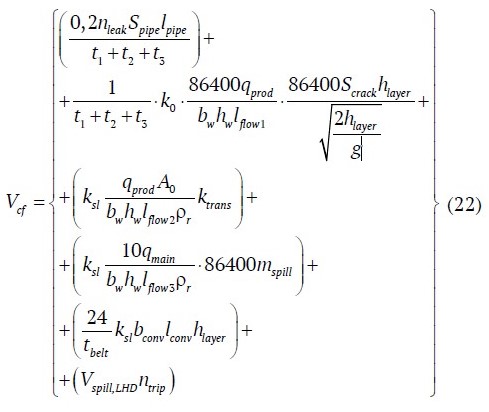
and
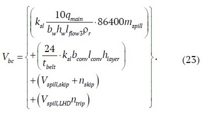
Thus, two mathematical models of sludge formation were developed, taking into account the specific conditions of the local mine drainage system and the characteristics of underground kimberlite ore mining.
Classification of sludge formation sources within the local mine drainage system in a kimberlite mine
The proportional contribution of each individual sludge formation source, Δi, to mine water contamination within the local drainage system of a kimberlite mine is determined as follows:
Δi = Vi/Vsludge · 100%, (24)
where Vi is the daily sludge volume from source i, m3; Vsludge is the total daily sludge volume, i.e., Vcf or Vbk, depending on the selected underground mining method for the kimberlite ore deposit, m3.
To determine the values of Vi and Vsludge, the previously derived mathematical models (22) and (23) are used.
Table 1 presents the calculated values of Vcf and Vbk, as well as their components, with reference to the Mir and Udachny kimberlite mines.
Table 1
Results of calculations of sludge formation volumes Vi, Vcf, and Vbk
Mir Mine | Udachny Mine | ||
Vflush = 3.96 m3 | Vspil l = 3.33 m 3 | Vspill = 23.19 m3 | VLHD = 0.14 m3 |
Vleak = 0.64 m3 | Vwash = 0.77 m 3 | Vwash = 0.0024 m3 | – |
Vexc = 4.84 m3 | VLHD = 0.01 m 3 | Vskip = 7.5 m3 | – |
Vcf = 13.55 m3 | Vbk = 30.83 m3 | ||
Fig. 1 shows the contribution of previously identified sludge formation sources to mine water contamination within the local drainage systems of the Mir and Udachny mines.
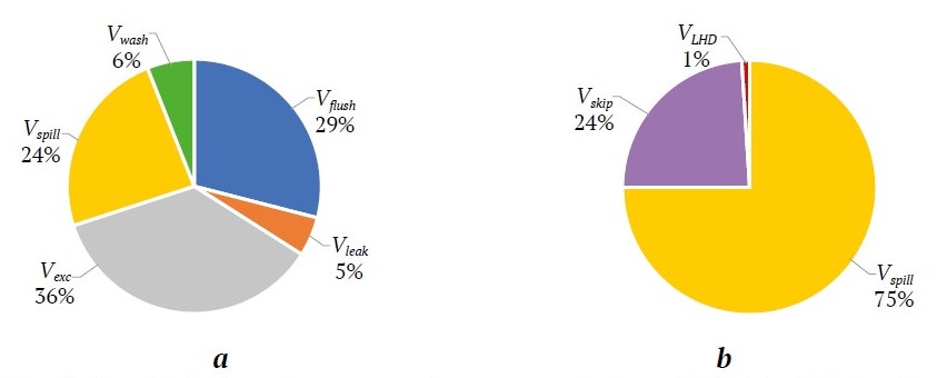
Fig. 1. Contribution of sludge formation sources to mine water contamination at the Mir (a) and Udachny (b) mines: 1 – Vflush; 2 – Vleak; 3 – Vexc; 4 – Vspill; 5 – Vwash; 6 – Vskip; 7 – VLHD
According to the conducted studies, the main contributors to mine water contamination at the Mir mine are sludge formation volumes Vexc, Vflush, and Vspill, while at the Udachny mine they are Vspill and Vskip. In both cases, Vspill represents a major contributor, accounting for 24% and 75% of the total sludge formation volume, respectively.
These findings are relevant to both operating and future water-bearing kimberlite mines operated by ALROSA.
Development and justification of a mechanized system for collecting spilled rock mass
To minimize the impact of sludge formation volume Vspill on mine water contamination under local drainage conditions at kimberlite mines, a mechanized system for collecting spilled kimberlite ore (hereinafter referred to as “the mechanized system”) has been developed. This system is most effectively installed in the ore transfer zone between the feeder and the conveyor belt, as the majority of spillage occurs beneath the conveyor in this area. This zone accounts for 65–70% of the total solid phase contributing to sludge formation volume Vspill.
In view of the above, it can be concluded that under conditions of underground kimberlite ore mining using backfilling systems, practical implementation of the proposed technological solution can reduce the intensity of mine water contamination in the local drainage system by approximately 16%. In mines that use block caving methods, the expected reduction may reach a factor of two.
The operating principle of the mechanized system is illustrated in Fig. 2 [19].
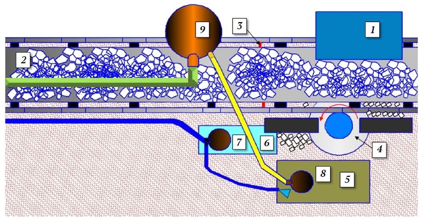
Fig. 2. Mechanized system for collecting spilled ore:
1 – feeder; 2 – belt conveyor; 3 – partition; 4 – collection and loading unit; 5 – sludge collector; 6 – water collector; 7 – submersible pump; 8 – submersible pump with agitator; 9 – pulp collection tank
During the transfer of kimberlite ore from feeder 1 to conveyor belt 2, the spilled rock mass accumulates on the floor of the level in an area separated from the rest of the under-conveyor space by partition 3. The collection and loading unit 4, mounted on the side of the conveyor support frame, gathers the spilled ore. Using rotating arms, this unit moves the sludge-forming material into the sludge collector 5. Mine water flowing into the level, which previously carried the spilled material toward the local drainage system, is now diverted into the water collector 6, thus avoiding contact with the settled solids. From the water collector, the water is pumped by submersible pump 7 into the local drainage facility’s water collectors. A portion of this water is systematically diverted via a branch of the pump 7’s discharge pipeline into the sludge collector 5, where it is mixed with the accumulated rock material by the agitator of submersible pump 8, forming a slurry. This slurry is then pumped into the pump collection tank 9. Through the tank’s drain valve, it is evenly redistributed onto the conveyor belt.
To control the flow of water into sludge collector 5, the end of the branch pipeline from pump 7 is equipped with a ball valve.
Submersible pumps 7 and 8 must be fitted with automated control systems to ensure timely startup and shutdown based on the fill levels of the water collector 6 and sludge collector 5.
The collection and loading unit consists of a gear motor 1, a disc 2, a shaft 3, arms 4, and couplings 5 (Fig. 3). The shaft, threaded at one end, is screwed into a central threaded hole in the disc. A coupling is mounted on the opposite end of the shaft. The arms are press-fitted into the disc slots. Components 2, 3, and 4 form the sweeping star. The gear motor is secured using bolted connections 6 inserted into slotted holes 7 of a channel section 8 welded to the side of the conveyor support frame 9. This slot design allows for both vertical and horizontal adjustment of the gear motor when connecting it to the sweeping star via the couplings.
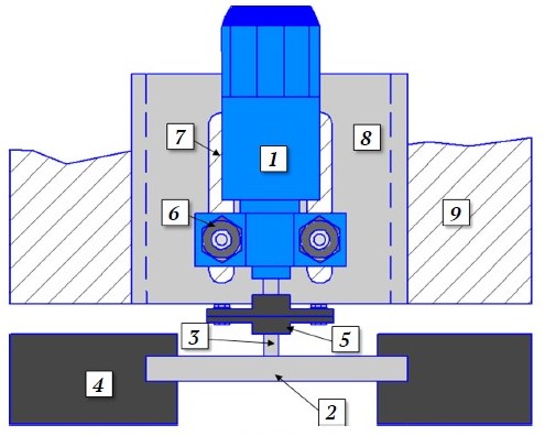
Fig. 3. Collection and loading unit:
1 – gear motor; 2 – disk; 3 – shaft; 4 – arm; 5 – coupling; 6 – bolted connection; 7 – slotted hole; 8 – channel section; 9 – side of the conveyor frame
To reduce the energy consumption of the unit, the arms 4 are made of lightweight materials such as wood or composites. Additionally, these materials are less susceptible to the aggressive effects of highly mineralised mine water.
The recommended ratios between the geometric parameters of the collection and loading unit components are as follows:
Rdisk : larm – 1 : 3; larm-in-slot : Rdisk – 1 : 2; barm : larm-in-slot – 1 : 4,
where Rdisk is the radius of the disk; larm is the length of the arm; larm-in-slot is the length of the arm section inserted into the disk groove; barm is the thickness of the arm.
The operating parameters of the collection and loading unit depend on the number of arms zstar, the diameter dstar, and the rotational speed nstar of the sweeping star [21, 22]. The number of arms zstar ranges from 1 to 8, and the rotational speed nstar is 24–45 rpm [22].
The operating costs of the mechanized system are largely determined by the electricity consumed by the gear motor of the collection and loading unit.
The power consumption of the gear motor PmotPmot, kW, is determined as follows:
Pmot = (M1 + M2)nstar/(9550η), (25)
where M1 is the static torque on the sweeping star, N · m; M2 is the resisting torque on the sweeping star, N · m; η is the efficiency of the gear motor.
The torque M1 is given by:
M1 = 2πInstar/(60ttime), (26)
where I is the moment of inertia of the sweeping star, kg · m2; ttime is the set time for acceleration or deceleration of the sweeping star, s.
The moment of inertia I is calculated as:
I = (mstar + mcoupling)R2star/2, (27)
where mstar is the mass of the sweeping star, kg; mcoupling is the total mass of the two couplings, kg; Rstar is the radius of the sweeping star, m.
The radius Rstar is determined as follows:
Rstar = Rdisk + larm + larm-in-slot, (28)
Since the spilled ore accumulates between the center and the far edge of the under-conveyor zone, the optimal radius Rstar is calculated using the following expression:
Rstar − dmot − bchan.sect ≥ bconv/2, (29)
where dmot is the diameter of the gear motor housing (m); bchan.sect is the width of the channel section, m; bconv is the width of the conveyor belt.
The torque M2 is calculated as follows:
M2 = kresistFcaptharmzstarρoregdstar, (30)
where kresist is the coefficient accounting for the resistance of the spilled ore encountered by the arm of the sweeping star during movement, depending on its moisture content w; Fcapt is the average capture area of spilled ore per arm of the sweeping star, m2; ρore is the ore density, kg/m3; g is gravitational acceleration, m/s2.
After multiplying Fcapt and harm, equation (30) takes the following form:
M2 = kresistVspillzstarρoregdstar, (31)
where Vspill is the average volume of spilled rock mass per second, m3.
Practical data obtained at the Udachny kimberlite mine indicate that the moisture content w of the spilled ore does not exceed 20%. Laboratory experiments using a physical model of the collecting arm demonstrated that the power consumption P required to handle wet material may increase by approximately 15% (at w = 20%) compared to the power required for handling dry material P0 (Fig. 4).
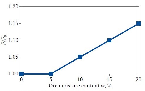
Fig. 4. Dependence of the P/P0 ratio on the moisture content w of the spilled ore
Based on the results of physical modelling, the coefficient kresist is assumed to be 1.15.
The volume Vspill is calculated as follows:
Vspill = kzonemspill/ρore, (32)
where kzone – coefficient accounting for the volume of spilled ore directly in the transfer zone from the feeder to the conveyor belt; mspill is the mass of the spilled ore per second, kg.
Estimation of the expected technical and economic effect from the implementation of research results (case study: Udachny Mine)
A significant portion of the solid phase of mine water usually settles at the bottom of drainage workings in the form of sludge and silt deposits. These are subsequently removed using LHD machines and, depending on the mining technology adopted for kimberlite deposits, either used as one of the components of the backfilling mixture or hoisted to the surface using shaft hoisting equipment [15].
A characteristic feature of the settled sludge pulp in drainage workings at kimberlite mines is the presence of voids filled with mine water. During removal of the pulp by the LHD machine’s bucket, these voids tend to rupture, causing water to spill. This leads to extensive contamination of the machine's units and components – particularly the suspension bearing of the articulated frame and the electrical equipment – resulting in a shortened service life.
Operational data show that the mean time to failure for such LHD machines is 30–40% lower than that of similar equipment used in other production areas of kimberlite mines.
Therefore, when calculating the main operating costs of the drainage system at a kimberlite mine, it is essential to factor in the annual repair costs of LHD machines (ZLHD, million RUB/year), which result from cleaning sludge-filled drainage workings and hauling the removed pulp:
ZLHD = kfailureZLHD*, (33)
where kfailure is the coefficient accounting for the average share of equipment failures caused by contact with sludge pulp (kfailure ≈ 0.35); ZLHD* is the total annual operating costs of the LHD machines.
According to statistical studies [16], the dependence of ZLHD on the volume of sludge material transported by LHD machines Vsludge, m3, is described by the following regression equation (Fig. 5).
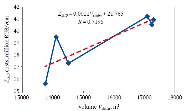
Fig. 5. Dependence of LHD repair costs ZLHD on the annual volume of transported sludge material V sludge
Implementation of the mechanized system is expected to significantly reduce ZLHD costs associated with mine water drainage operations at kimberlite mines.
Its estimated payback period Tpayback, months, is calculated as follows:
Tpayback = (Z1 + Z2)/ΔZLHD · 12, (34)
where Z1 is the estimated cost of developing and installing the system, million RUB; Z2 is the estimated operating cost of the system, million RUB; ΔZLHD – difference between the current and expected LHD repair costs ΔZLHD after implementation of the system.
The expected annual technical and economic benefit Z0 from the practical implementation of the proposed technological solution (after the payback period) is determined by the following expression:
Z0 = ∆ZLHD – Z2. (35)
According to the calculations, implementation of the mechanized system at the Udachny mine is expected to pay off within 10 months. The projected annual technical and economic benefit from its use is estimated at 4 million RUB.
Given that the implementation of the proposed technological solution eliminates the need to purchase an additional loading and hauling machine for the drainage system at the studied mine, its expected technical and economic efficiency increases significantly.
Conclusion
The following key findings were obtained based
on the research results:
- Mathematical models of sludge formation within the local mine drainage system of a kimberlite mine were developed, allowing for the identification of the main sources of suspended solids in mine water, depending on the adopted ore extraction technology. It was found that at mines employing backfilling of mined-out voids, the primary sources of mine water contamination are:
– sludge generated from flushing blocked sections of the backfilling pipeline (29%);
– sludge from continuous miner operations (36%);
– sludge formed due to ore spillage during its transfer from the feeder to the conveyor belt at the main haulage level (24%).
At mines that extract kimberlite ore using block caving, the dominant source of contamination is ore spillage from the conveyor belt, accounting for 75% of the total sludge volume. - To reduce the rate of mine water contamination within local drainage systems at kimberlite mines, a mechanized system for collecting spilled rock mass from the under-conveyor area was proposed. The system’s working unit – a collection and loading device – is mounted in the ore transfer zone between the feeder and conveyor belt. In the context of underground mining with backfill systems, the implementation of this system is expected to reduce mine water contamination intensity by approximately 16%, and by a factor of two at mines employing block caving. The estimated payback period for the technological solution is less than one year (10 months), and the projected annual technical and economic benefit is 4 million rubles (based on data from the Udachny Mine).
References
1. Palamarchuk N. V., Solomin A. P., Krutous N. S. Reserves for increasing the efficiency and reliability of centrifugal sectional pumps with axial balancing of the rotor. Collection of scientific papers of the Donetsk Institute of Railway Transport. 2023; (69):74–90. (In Russ.)
2. Senkus V. V., Stefanyuk B. M. Investigation of the sludge deposition process in sedimentation tanks. Minerals and Mining Engineering. 2006;(5):54–62. (In Russ.)
3. Timukhin S. A., Dolganov A. V., Popov Yu. V. et al. On the development of the mine sectional centrifugal dual-stream pumps. News of the Ural State Mining University. 2014;2(34):39–41. (In Russ.)
4. Aleksandrov V. I., Gorelkin I. M. Hydraulic calculation of the mine drainage system´ pipeline of the taking into account pressure losses for the transportation of solid particles. Mining Equipment and Electromechanics. 2013;(7):44–47. (In Russ.)
5. Zaripov A. H. Assessment of the energy efficiency of drainage installations and compressed air supply systems. Minerals and Mining Engineering. 2010;(4):74–77. (In Russ.)
6. Olizarenko V. V., Mingazhev M. M. Determination of silting time and frequency of cleaning of the main reservoirs of underground mines. Mining Informational and Analytical Bulletin. 2010;(7):27–30. (In Russ.)
7. Dolganov A.V. Energy efficiency improvement during operation of mine waterlets. Mining informational and analytical bulletin 2019;5(S9):16–23. (In Russ.) https://doi.org/10.25018/0236-1493-2019-5-9-16-23
8. Zotov V. V., Mnatsakanyan V. U., Bazlin M. M. et. al. Extending the service life of centrifugal dewatering pump impellers in mines. Russian Mining Industry. 2024;(2):143–146. (In Russ.) https://doi.org/ 10.30686/1609-9192-2024-2-143-146
9. Dolganov A. V. Hydroabrasive wear and profitability of water-dranaige installations in mine and ore mines. Mining informational and analytical bulletin. 2019;5(S9):3–8. (In Russ.) https://doi.org/10.25018/0236-1493-2019-5-9-3-8
10. Razumnyi Yu. T. Ruxlova N. Yu., Ruxlov A. V. Energy efficiency of the main drainage of the coal mine. Dnepropetrovsk: National Mining University; 2016. 109 p. (In Russ.)
11. Uralov B., Berdiev S., Rakhmatov M., et. al. Theoretical models and dependences for calculating intensity of hydroabrasive wear of pump working parts. In: E3S Web of Conferences. 2023;(365):03019. http://dx.doi.org/10.1051/e3sconf/202336503019
12. Deng L., Hu Q., Chen J., et al. Particle Distribution and Motion in Six-Stage Centrifugal Pump by Means of Slurry Experiment and CFD-DEM Simulation. Journal of Marine Science and Engineering. 2021;9(7):716. http://dx.doi.org/10.3390/jmse9070716
13. Dolganov A. V., Timukhin S. A. Hydroabrasive wear of mine drainage pumps. Moscow: Academy of Natural Sciences Publ.; 2016. 180 p. (In Russ.)
14. Korpachev V. V., Kharkov A. V., Berezin S. E. Slurry pond cleanout technology with the application of submersible pumps. Russian Mining Industry. 2013;1(107):58. (In Russ.)
15. Ovchinnikov N. P. Influence of silt-slurry pulp on the efficiency of mining machines. Izvestiya Tula State University. Sciences of Earth. 2022;(2):348–356. (In Russ.) https://doi.org/10.46689/2218-5194-2022-2-1-348-356
16. Ovchinnikov N. P., Zyryanov I.V. Integrated assessment of mine water pollution influence on water removal efficiency in Udachny Mine. Gornyi Zhurnal. 2022;(7):95–99. (In Russ.) https://doi.org/10.17580/gzh.2022.07.16
17. Ryl'nikova M. V., Olizarenko V. V., Mingazhev M. M. Improving the technology of drainage and in the underground development of deposits of copper-pyrite ores with filling hardening mixture. Geological Survey Bulletin. 2012;2(88):16–20. (In Russ.)
18. Semakin M. S. Skips of high operational reliability. Mining informational and analytical bulletin. 2013;(12):145–147. (In Russ.)
19. Ovchinnikov N.P. Development and justification of a complex for collecting spilled rock mass. Izvestiya Tula State University. Sciences of Earth. 2023;(4): 457–464. (In Russ.)
20. Bibikov P. Ya. Cleaning the conveyor belt, a look at the problem. Mining informational and analytical bulletin. 2004;(3):300–302. (In Russ.)
21. Afonina N. B., Otrokov A. V., Khazanovich G. Sh. On the question of the appointment of separate parameters of the roadheaders gathering-stars loading organs. Russian Mining Industry. 2021;(5):90–93. (In Russ.) https://doi.org/10.30686/16099192-2021-5-90-93
22. Otrokov A. V., Khazanovich G. S., Afonina N. B. Impact of design parameters on the efficiency of loading organs with gathering stars of the roadheaders. In: Proceedings of the 4th international conference on industrial engineering ICIE: Springer; 2018. Pp. 401–410. https://doi.org/10.1007/978-3-319-95630-5_44
About the Author
N. P. OvchinnikovRussian Federation
Nickolay P. Ovchinnikov – Cand. Sci. (Eng.), Associate Professor, Director of the Mining Institute
Yakutsk
Scopus ID 57191629443
Review
For citations:
Ovchinnikov N.P. Reducing mine water contamination at the local drainage facility of a kimberlite mine. Mining Science and Technology (Russia). 2025;10(2):169-179. https://doi.org/10.17073/2500-0632-2024-07-274


