Scroll to:
Stability of a controlled sucker-rod pump unit drive under operating conditions and during voltage dips in the electrical network
https://doi.org/10.17073/2500-0632-2024-01-213
Abstract
The use of a variable frequency drive (VFD) for sucker-rod pump units (SRPUs), widely employed in oil extraction, enhances the energy and technological efficiency of oil production and reduces equipment wear. However, its application is hindered by unstable operation under insufficient balancing of the SRPU and sensitivity to short-term voltage dips, which frequently occur in the extensive electrical networks of oil fields. Insufficient balancing of the SRPU leads to the occurrence of a period within the pumping cycle where the motor operates in generator mode, caused by the unevenness and reversal of the resistance torque of the working mechanism. The motor’s transition to generator mode, as well as voltage dips in the power supply, causes the voltage in the DC link of the VFD to exceed the set limits, resulting in the drive being shut down. To investigate the processes during the operation of sucker-rod pump units and to test methods for mitigating the negative impact of generator mode and voltage dips in the power supply network on the VFD, a model of the “power grid – variable frequency SRPU drive” system with a load characteristic of this application was developed in Matlab Simulink. A series of experiments were conducted, and the results were analyzed. The suppression function of the generator mode was examined, and the feasibility of its application to real SRPUs was evaluated. The use of an uninterruptible power supply system based on battery energy storage to prevent operational interruptions during different levels of power supply voltage dips was analyzed. The resulting model can be used for general analysis of operability and stability, as well as for verifying the correct selection of key elements in the design of sucker-rod pump unit systems with variable frequency drives.
Keywords
For citations:
Ershov M.S., Efimov E.S. Stability of a controlled sucker-rod pump unit drive under operating conditions and during voltage dips in the electrical network. Mining Science and Technology (Russia). 2024;9(3):292-303. https://doi.org/10.17073/2500-0632-2024-01-213
Stability of a controlled sucker-rod pump unit drive under operating conditions and during voltage dips in the electrical network
Introduction
To enhance the technological and energy efficiency of sucker-rod pump units (SRPUs), widely used in oil extraction, they are equipped with a variable frequency drive (VFD). However, its application is constrained by instability during operation under conditions of insufficient balancing of pump jacks and frequent disturbances in the electrical networks of oil fields.
The practical application of VFDs in SRPUs has shown that the main causes of drive instability are short-term voltage dips in the electrical networks of oil fields and the presence of a generator mode period during the pumping cycle. This mode arises due to the uneven load caused by the inertia and vibration loads resulting from the movement of the rod string. A brief generator mode during pumping can occur even in well-balanced units with shallow pump depths and, consequently, low rod suspension force created by the weight of the fluid column when the difference between maximum and minimum loads per cycle is small. When transitioning to generator mode, the energy received from the motor through the inverter cannot be recovered into the grid via the uncontrolled rectifier of the frequency converter (FC). This leads to an increase in the DC link voltage, which subsequently results in the FC shutting down due to its built-in overvoltage protection [1].
To improve stability and prevent undesirable emergency shutdowns of the VFD in SRPUs during generator mode, several solutions can be employed: using a frequency converter with energy recovery capability, installing a braking resistor, or utilizing special software settings. Implementing a regenerative FC is associated with significant capital investment due to the use of an active rectifier. Installing a braking resistor results in the unproductive consumption of recoverable energy, which is dissipated as heat. The software setting known as the anti-regeneration function (ARF) increases motor speed, which can lead to undesirable dynamic forces within the SRPU. Each method has its advantages and disadvantages, leading to ambiguity in solving the problem of the negative impact of generator mode on FC operation.
Another feature of VFDs is their increased sensitivity to power supply disruptions, particularly to voltage dips [2]. In the event of a significant voltage drop in the DC link, the FC will disconnect from the grid due to the activation of undervoltage protection, which is necessary to prevent a current surge when the capacitor charges after the voltage is restored [3]. Enhancing the reliability of SRPU operation during voltage dips can be achieved through the use of an uninterruptible power supply (UPS) system connected to the DC link.
In accordance with the identified problems and their potential solutions, modeling was conducted to examine methods for eliminating overvoltage in the DC link that occurs during the operation of VFDs in SRPUs, as well as the application of UPS systems to maintain operation during power supply voltage dips to determine the impact of these solutions on system stability.
Methods
To investigate methods for mitigating the impact of generator mode and voltage dips on the operation of the VFD, a simulation of the electrical complex of the sucker-rod pump unit was performed in Matlab Simulink (Sim Power Systems library). A model was developed, whose main components include: a section of the electrical network, a frequency converter, a squirrel-cage induction motor, a four-bar linkage pump jack mechanism, a well, as well as a bidirectional DC converter (DC/DC converter) and a lead-acid battery (LAB).
The electrical system includes a power source with a short-circuit capacity of Sshc = 100 MVA; an overhead line (6 kV) 6 km in length, with an aluminum conductor cross-section of 16 mm²; a 6/0.4 kV transformer with a capacity of 40 kVA; a cable line from the transformer to the frequency converter, 20 m in length, with aluminum cores of 10 mm² cross-section; a frequency converter based on an uncontrolled rectifier and a three-phase inverter controlled by pulse-width modulation (PWM); and a squirrel-cage induction motor with two pole pairs, whose parameters include: nominal power Pnom = 30 kW; nominal speed nnom = 1485 rpm; nominal efficiency η=0.91; power factor cos φ=0.86; nominal current Inom = 60 A; starting current ratio is = 7.7; starting torque ratio ms=2.7; maximum torque ratio mmax = 3.2 m; and moment of inertia J = 0.1326 kg∙m². In this model, the VFD is controlled by a scalar control method with the motor speed being maintained at the setpoint.
The mathematical model of the squirrel-cage induction motor is represented by the system of equations (1), which is constructed for the rotor-aligned (dq-axes) two-phase orthogonal coordinate system. The mechanical part of the drive is represented by equation (2). The calculation of the equivalent circuit parameters used in the model is performed using the formulas presented in [4].
The sucker-rod pump unit was modeled for an axial-type pump jack, the kinematic diagram of which is shown in Fig. 1 [5, 6]. The following designations are used in Fig. 1: R – crank; P – connecting rod; C – rear arm of the balance beam; A – front arm of the balance beam. Additionally, auxiliary lengths and angles used in the modeling are presented.
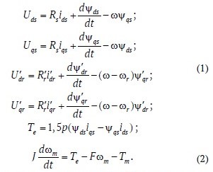
The variables in equations (1) and (2) have the following designations: Uds, ids – projections of stator voltage and current on the d-axis; U′qs, i′qs – projections of stator voltage and current on the q-axis; U′dr , i′dr – projections of rotor voltage and current on the d-axis; U′qr , i′qr – projections of rotor voltage and current on the q-axis; ψds, ψqs – projections of stator flux linkage on the d and q axes; ψ′dr, ψ′qr – projections of rotor flux linkage on the d and q axes; Rs, – active resistances of the stator and rotor windings; Te, Tm – electromagnetic torque of the motor and the torque resistance of the mechanism referred to the motor shaft; ω, ωm и ωr – angular velocity of the coordinate system, mechanical angular velocity of the motor shaft, and electrical angular velocity of the motor rotor; J, F – moment of inertia and viscous friction coefficient of the rotor and load.
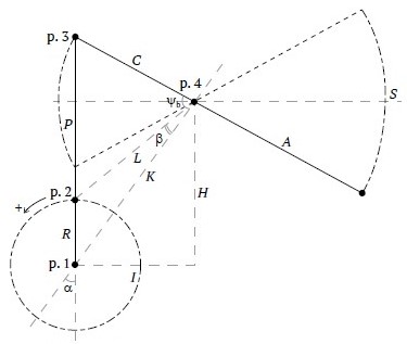
Fig. 1. Axial kinematic diagram of the pump jack
The operation of the sucker-rod pump unit (SRPU) is cyclical. An example of a dynamogram of normal operation is shown in Fig. 2, a, where the following periods are indicated [7]:
A–B – The beginning of the upward movement of the rod string, during which the load (the weight of the fluid column) is transferred from the tubing to the rod string. The tubing shortens, and the rod string lengthens, while the pump valves are closed.
B–C – The upward movement of the rod string continues after the load transfer process is completed. The intake valve opens, allowing fluid to enter the pump cylinder.
C–D – The intake valve closes at the uppermost position of the rod string, marking the beginning of the downward movement of the rod string. The load is transferred from the rod string back to the tubing. The tubing lengthens, and the rod string shortens, with the pump valves closed.
D–A – The downward movement of the rod string continues after the load transfer process is completed. The discharge valve opens. The cycle completes at the lowermost position.
Fig. 2, b presents a diagram showing the dependence of the pumping periods on the crankshaft angle, with the cycle divided into 4 quadrants. This representation is more convenient for adjusting the control settings of the unit.
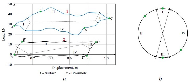
Fig. 2. Periods of the pumping cycle: а – on surface and downhole ; b – on the diagram of the polished rod position relative to the crankshaft angle
As is well known, even the operation of a well-balanced pump jack can be accompanied by the motor transitioning into a brief generator mode during the first and third periods of the pumping cycle, as shown in Fig. 2. The duration of this mode may increase when the parameters of the SRPU change during operation due to equipment wear [1].
In the model of the sucker-rod pump unit, which includes the gearbox, the four-bar linkage pump jack mechanism, and the downhole section, the cyclic nature of the load, intake pressure, fluid density, dynamic fluid level in the well, the weight of the rod string in the fluid, the weight of the fluid column, the degree of balance of the pump jack, as well as the stroke loss of the rod suspension point, which is associated with elastic elongations during load transfer from the tubing string to the rod, are all considered [8, 9].
The equations and dependencies used in the mathematical model allow tracking the position, speed, and acceleration of the rod string suspension point based on the geometric dimensions of the pump jack mechanism. They also allow determining the coefficient for calculating the resistance torque on the crankshaft based on the load at the suspension point [10, 11].
Thus, the developed model allows evaluating the operating modes of the SRPU with different loads and degrees of pump jack balance, determining the energy consumed from the grid, and the energy dissipated on the braking resistor in the DC circuit of the VFD during the motor's generator mode, which occurs when the rod string moves downward under its own weight.
The model is supplemented with an uninterruptible power supply (UPS) system, and there are many implementation schemes. The simulation considers a system that consists of a DC/DC converter connected to the DC link of the SRPU's frequency converter. The DC/DC converter is similar to the inverter of the frequency converter, with the difference being in the control system and the law governing the control signals for the operation of the IGBT switches [12]. Inductors and battery packs (LABs) are connected to the output of the DC/DC converter, with the quantity and connection scheme depending on the duration of the backup. The control system must generate the gate drive signals for the power switches in such a way as to maintain the required voltage level in the DC link and regulate the charging and discharging current and voltages of the battery packs. It consists of an internal loop with current feedback from the DC/DC side of the battery pack and an external loop with feedback from the DC link voltage of the VFD during discharge and from the battery pack voltage during charging [13].
There are several types of battery models available: those based solely on experimental data, those relying on a mathematical description of chemical processes, and those utilizing electrical equivalent circuit models. For the simulation, the third type was employed, with a model available in the standard Simulink library. The parameters required for this model can be determined using technical specifications and discharge characteristics provided by the manufacturer [14]. However, the most precise calibration can be achieved by conducting real-world tests on the specific battery in question.
In the control system, the voltage range on the battery side is set between 310–435 V, and the voltage range on the DC link side of the VFD is set between 495–550 V. The maximum error for the LAB model in the standard Simulink library is 5% for a charge level range from 10% to 100%, with currents ranging from 0 to twice the battery capacity during charging, and from 0 to five times the battery capacity during discharging. The assumptions for the considered LAB model are as follows:
- the internal resistance does not change with current amplitude and remains constant throughout the charge and discharge cycles;
- discharge and charge characteristics are identical;
- the battery capacity does not change with current amplitude, and the Peukert effect [15] is absent;
- self-discharge of the LAB is not implemented in this model, but it can be realized by adding a large resistor in parallel with the battery terminals;
- the LAB does not have a memory effect.
The parameters for the LAB system of 32 units are selected to maintain operation for a 30 kW load for 5 minutes, with each battery maintaining a voltage of 10.8 V. For this, it is required that during discharge at constant power, each LAB in the system must provide, W/battery:

Catalog data from various manufacturers indicate that for the case under consideration, a system of 32 LABs with a nominal capacity of 33 Ah each can sustain a discharge at constant power of 1020 W/battery. The parameters set in the model are similar to such a system of 32 LABs.
SRPU simulation results
The operation of the sucker-rod pump unit with a period of generator mode was simulated. Fig. 3 shows the graphs for a pump jack with a significant imbalance of approximately 50%, with the degree of imbalance determined using the current imbalance coefficient [16, 17]. Using the lower graph in Fig. 3, the beginning of the generator mode can be identified at 8.2 seconds when the load torque on the crankshaft becomes negative. On the upper graph, curve 1 represents the power dissipated on the braking resistor, and curve 2 represents the DC link voltage, which is limited to 757 V. When this value is reached, the braking resistor circuit is activated, and the excess energy is dissipated.
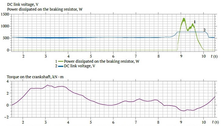
Fig. 3. DC link voltage and power dissipation curves on the braking resistor (upper graph), and the torque curve on the crankshaft considering the effect of counterweights (lower graph) at approximately 50% imbalance
For different levels of imbalance, Figs. 4 and 5 show the DC link voltage curves on the upper graphs: curve 1 corresponds to constant speed (without ARF), and curve 2 corresponds to active ARF. To more clearly indicate the period of ARF activation, the speed graphs, labeled as curve 3, are shown in the lower part of these Fig.s. Additionally, curve 1 denotes the power dissipated on the braking resistor without ARF, and curve 2 denotes the power dissipated with active ARF.
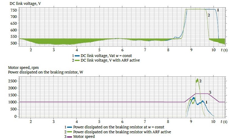
Fig. 4. DC link voltage curves (upper graph), speed and power dissipation curves on the braking resistor (lower graph) with ARF disabled and active, at approximately 50% imbalance
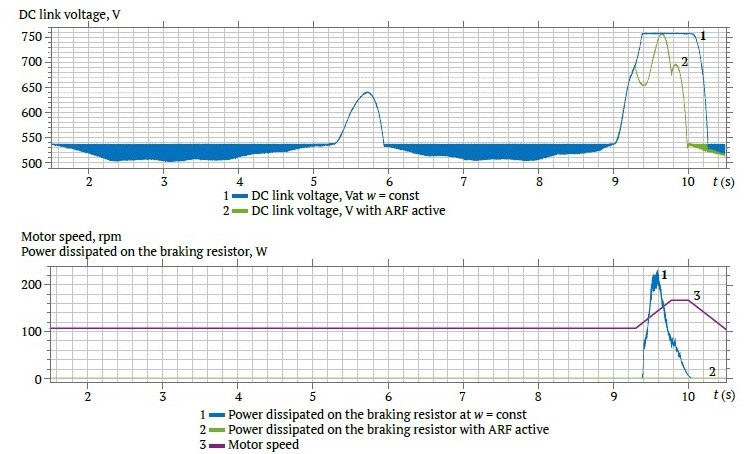
Fig. 5. DC link voltage curves (upper graph), speed and power dissipation curves on the braking resistor (lower graph) with ARF disabled and active, at approximately 5% imbalance
Simulation results of voltage dips and the operation of the DC/DC converter
Disturbances in the electrical network are caused by short circuits, originating from nearby overhead transmission lines and from distant networks of 35 kV and above. The simulation of nearby short circuits was carried out at the node connected to the 6 kV overhead transmission line. It was found that during single-phase short circuits in the 6 kV network, the drive operation can continue. However, three-phase and two-phase short circuits in the 6 kV network lead to shutdowns, with the SRPU's VFD losing power. In the case of a two-phase short circuit not being cleared, large voltage fluctuations occur in the DC link, as shown in Fig. 6, a, and large current fluctuations at the VFD input, as shown in Fig. 6, b, which are highly likely to cause equipment failure. It should be noted that when the 6/0.4 kV transformer windings are connected in a ∆/Y0–11 configuration, the average voltage in the VFD's DC link is higher than when the transformer windings are connected in a Y/Y0–12 configuration. In the event of a power supply not being disconnected during emergency conditions, individual drive protection should be activated. It is recommended to use both an automatic circuit breaker and a fast-acting fuse that match the drive's nominal parameters to ensure comprehensive protection.
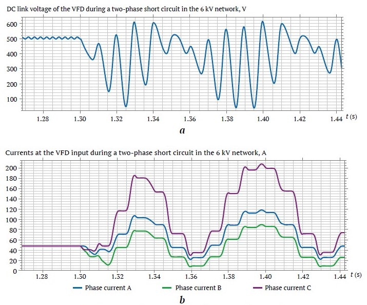
Fig. 6. Two-phase short circuit in the 6 kV power supply network: a – DC link voltage of the VFD; b – input current of the VFD
Distant short circuits manifest in 6 kV load nodes and at the VFD inputs as voltage dips. To maintain the operation of the VFD with centrifugal working mechanisms, an effective means of improving stability is the "kinetic reserve" option [18], which essentially functions as the reverse of the anti-regeneration function mentioned earlier. The "kinetic reserve" option causes an accelerated reduction in motor speed by lowering the set frequency at the VFD output, with the excess motor energy being used to maintain the voltage in the DC link.
In the drive system of the SRPU, the use of the "kinetic reserve" option would be ineffective because the resistance torque of the mechanism does not depend proportionally on the square of the speed, as it does in centrifugal mechanisms, but follows a more complex law dependent on the position of the suspension point. The implementation of this option is only possible during a short period of the cycle. Therefore, the possibility of connecting a UPS system based on a DC/DC converter and LABs to the VFD's DC link was investigated.
Typically, the VFD has built-in protection against voltage dips in the DC link—undervoltage protection (UVP), which is set by default within the range of 64-76% to 85-90% of the nominal voltage value [3]. The voltage level is determined by the permissible current value of the rectifier diodes during power restoration and the surge of the DC link capacitor charging current, which is mitigated by connecting the capacitor charging circuit. The voltage level is also related to the minimum allowable voltage necessary to maintain the normal operating mode of the of the sucker-rod pump unit.
The operation was simulated with a reduction in the DC link voltage to 0.7 of the nominal value. Fig. 7, a shows the voltages for two modes, and Fig. 7, b shows the corresponding motor speeds.
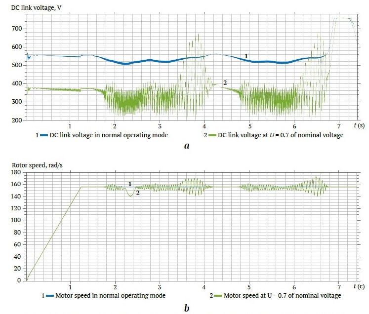
Fig. 7. For two operating modes: 1 – at nominal voltage and 2 – with a voltage reduction to 0.7 of the nominal value, the following curves are presented: a – DC link voltage; b – motor speed
Fig. 8 shows the results of simulating a prolonged voltage dip in the DC (Uпч = 0.7Uпчном), link with the UPS connected to the DC link – curve number 2. The created model with the UPS is capable of maintaining the DC link voltage during voltage dips without causing negative oscillations in the motor shaft.
Fig. 9 presents the DC link voltage and the LAB voltage for the experiment, where the following voltage dip periods were used Uпч = 0.3Uпчном : 2–3 s; 4.1–5.1 s; 6.8–7.1 s.
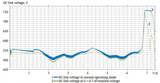
Fig. 8. DC link voltage in normal mode – curve 1, and in mode with a reduction of input voltage to 0.7 of the nominal value with the UPS connected – curve 2
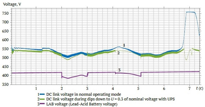
Fig. 9. DC link voltage and LAB voltage during short-term dips in input voltage in all three phases down to 0.3 of the nominal value with the UPS connected
Results and discussion
Based on the experiments conducted, it can be concluded that the anti-regeneration function (ARF) can completely eliminate the generator mode only when it is necessary to dissipate a small amount of power, as shown in Fig. 5. The acceleration settings when using the overvoltage suppression and speed and torque limiting functions must be conFig.d with regard to the actual characteristics of the well and equipment, as in some cases, an increase in speed may lead to unacceptable mechanical stresses in SRPU parts. The ARF reduces the duration of the pumping cycle, which should be considered when planning the operation mode of the unit.
The electromagnetic torque exerts a braking effect on the rotor in generator mode, but with the ARF active, the electromagnetic torque remains rotational. When ARF is active, the electromagnetic torque and the resistance torque, which becomes negative during the downward movement of the rod string, increase the motor speed, and the deceleration of the rod string at the end of the downward stroke occurs more intensively and rapidly [1]. The simulation results confirm that the longer the generator mode lasts, the higher the instantaneous rotor speed must be. The lack of speed limitation with active ARF can lead to acceleration to a speed that exceeds the nominal by 50-70%, if this is permissible for the motor. Increased speed dynamics at the end of the fourth and the first period of the pumping cycle lead to additional inertial forces in the pump jack elements and dynamic impacts on the pump jack structure, which increases wear and leads to the failure of the unit. Thus, ARF without the additional use of braking resistors can be successfully applied if it does not lead to a critical increase in load; that is, for SRPUs with a short generator mode period, where significant speed increases are not required to eliminate it, or when the motor operates at a speed significantly lower than the nominal speed maintained by the VFD.
It should be noted that in the absence of the ability to transfer excess energy to the grid, it is recommended to use a braking resistor even with an active anti-regeneration function, if there is no complete confidence that the operating mode will not change over time and the generator mode period will not increase. It should also be considered that an overvoltage in the DC link can be caused not only by transitioning to generator mode, so it is recommended to take measures to reduce the likelihood of other causes, such as high output voltage, voltage spikes at the VFD output, incorrect grounding connection, motor malfunction, and others.
When the voltage decreases, torque oscillations increase, as shown in Fig. 7, b, where increased oscillations and the appearance of speed dips can be observed. The model under consideration did not use DC link undervoltage protection or VFD overload protection, which could be triggered under these conditions. Further voltage reduction leads to an even greater decrease in the stability of the unit and subsequent motor shutdown. Therefore, a UPS is recommended to maintain operation in the presence of significant voltage dips or short-term interruptions.
The UPS simulation results presented in Fig.s 8 and 9 demonstrated its effectiveness during both prolonged voltage dips in the power supply network and short-term dips. The obtained results are close to ideal, and measurements taken on a real object or physical modeling of the UPS with such a load will allow adjustments to be made to this model if necessary.
It should be noted that the considered lead-acid batteries (LABs) have several limitations and requirements related to depth of discharge, voltage, and charge current at different battery charge levels, parameters for operation in buffer mode, temperature range, and the need for temperature compensation of the charging voltage. These requirements are specified in the LAB manual and should be considered by the charge and discharge management system—the DC/DC converter control system—to ensure the maximum possible service life. An alternative option is supercapacitors, which generally have a longer service life, can operate in a wider temperature range, and have fewer restrictions on permissible voltage, current, and charge levels. Detailed specifications are usually provided in the datasheets and catalogs for the respective equipment.
Future research directions may involve improving the accuracy of this model and examining the possibility of using a dynamic voltage distortion compensator (DVD compensator) with the SRPU VFD to compensate for voltage deviations and dips.
Conclusion
A model was developed to analyze the stability of the variable frequency drive (VFD) of a sucker-rod pump unit (SRPU), which takes into account the cyclical and uneven nature of the load, the balance of the pump jack, processes associated with the occurrence of generator mode, and the impact of voltage dips in the network. The method of eliminating overvoltage in the DC link by using the overvoltage suppression function was examined. It was determined that this function has several limitations, primarily related to the duration of the generator mode (degree of imbalance) and the period of its occurrence in the pumping cycle. With significant imbalance, the ARF will be less effective, and the use of a braking resistor will be required. If the generator mode occurs at the end of the upward or downward movement of the rod string, the increase in rotational speed will lead to undesirable mechanical forces, additional wear, or even equipment failure.
Another task of the study was to simulate voltage dips in the power supply network and examine their impact on the stability of SRPU operation. With minor voltage dips, the VFD is able to remain operational, and in some VFD models, special control algorithms are applied to maintain operational stability. It is known that with more significant voltage dips, the undervoltage protection (UVP) will activate. One way to maintain operation even during a short-term loss of voltage is through the use of an uninterruptible power supply (UPS). The operation of such a system was examined during the simulation, the results of which demonstrated the effectiveness of this method in improving operational stability. The model developed in this study can be used to perform a general assessment of the operability of a similar designed system and to verify the correct selection of the DC link capacitor and inductors at the input of the DC/DC converter.
References
1. Yarish R. F., Garifullina A. R., Garifullin R. I., Yakunin A. N. Investigation of operating modes of frequency-regulated electric drive of pumpjack. Power Engineering: Research, Equipment, Technology. 2018;20(11–12):56–64. (In Russ.) https://doi.org/10.30724/1998-9903-2018-20-11-12-56-64
2. Egorov A. V., Ershov M. S. Experimental study of the stability of asynchronous variable-speed drives (VSD) during short-term voltage failures. Industrial Power Engineering. 2018;(4):9–12. (In Russ.)
3. Xu Y., Lu W., Wang K. et al. Sensitivity of low-voltage variable-frequency devices to voltage sags. IEEE Access. 2019;7:2068–2079. https://doi.org/10.1109/ACCESS.2018.2885402
4. Pantel O. V. Method of calculating the parameters of an asynchronous motor to model its operating modes in the Matlab / Simulink environment. Academy. 2015;2(2):7–11. (In Russ.)
5. Haisen Z., Yilong W., Yang Z. et al. Practical model for energy consumption analysis of beam pumping motor systems and its energy saving applications. In: 2017 IEEE Industry Applications Society Annual Meeting. 1–5 October 2017, Cincinnati, OH, USA. Pp. 1–9. http://dx.doi.org/10.1109/IAS.2017.8101721
6. Zheng B., Gao X., Li X. Fault detection for sucker rod pump based on motor power. Control Engineering Practice. 2019;86:37–47. https://doi.org/10.1016/j.conengprac.2019.02.001
7. Fakher S., Khlaifat A., Hossain M. E., Nameer H. A comprehensive review of sucker rod pumps’ components, diagnostics, mathematical models, and common failures and mitigations. Journal of Petroleum Exploration and Production Technology. 2021;11:3815–3839. https://doi.org/10.1007/s13202-021-01270-7
8. Ershov M. S., Efimov E. S. Modeling of the energy efficiency of an electric drive for a rod pumping unit. In: Martynov V. G. (ed.) Gubkin University in Addressing Issues of the Russian Oil and Gas Industry: VI Regional Scientific and Technical Conference dedicated to the 100 th Anniversary of M. M. Ivanov. September 19–21, 2022, Moscow. Abstracts of Reports, Moscow: Gubkin Russian State University of Oil and Gas (NRU); 2022. Pp. 766–767. (In Russ.)
9. Langbauer C., Langbauer T., Fruhwirth R., Mastobaev B. Sucker rod pump frequency-elastic drive mode development – from the numerical model to the field test. Liquid and Gaseous Energy Resources. 2021;1(1):64–85. https://doi.org/10.21595/lger.2021.22074
10. Urazakov K. R., Molchanova V. A., Tugunov P. M. Method for calculating dynamic loads and energy consumption of a sucker rod installation with an automatic balancing system. Journal of Mining Institute. 2020;246:640–649. (In Russ.) https://doi.org/10.31897/PMI.2020.6.6
11. Solodkiy E. M., Kazantsev V. P., Dadenkov D. A. Improving the energy efficiency of the sucker-rod pump via its optimal counterbalancing. International Russian Automation Conference (RusAutoCon). 8–14 September 2019, Sochi, Russia. Pp. 1–5. https://doi.org/10.1109/RUSAUTOCON.2019.8867737
12. Higure H., Hoshi N., Haruna J. Inductor current control of three-phase interleaved DC-DC converter using single DC-link current sensor. In: 2012 IEEE International Conference on Power Electronics, Drives and Energy Systems (PEDES). 16–19 December 2012, Bengaluru, India. Pp. 1–5. https://doi.org/10.1109/PEDES.2012.6484495
13. Nandankar P., Rothe J. P. Design and implementation of efficient three-phase interleaved DC-DC converter. In: 2016 International Conference on Electrical, Electronics, and Optimization Techniques (ICEEOT). 3–5 March 2016, Chennai, India. Pp. 1632–1637. https://doi.org/10.1109/ICEEOT.2016.7754962
14. Tremblay O., Dessaint L.-A. Experimental validation of a battery dynamic model. World Electric Vehicle Journal. 2009;3(2):289–298. https://doi.org/10.3390/wevj3020289
15. Cugnet M., Dubarry M., Liaw B. Y. Peukert’s law of a lead-acid battery simulated by a mathematical model. ECS Transactions. 2010;25(35):223–233. https://doi.org/10.1149/1.3414021
16. Zyuzev A. M., Bubnov M. V. Diagnostics of the balance of the rod deep-well pumping unit by wattmetrogram. Bulletin of the Tomsk Polytechnic University. Geo Assets Engineering. 2019;330(4):178–187. (In Russ.) https://doi.org/10.18799/24131830/2019/4/226
17. Galeev A. S., Nurgaliev R. Z., Bikbulatova G. I., Sabanov S. L., Boltneva Yu. A. Criterion of equilibrium of the slow-speed drive of the downhole rod pumping unit to improve the reliability of the gearbox. Petroleum Engineering. 2019;17(6):96–101. (In Russ.) https://doi.org/10.17122/ngdelo-2019-6-96-101
18. Belousenko I. V., Ershov M. S., Chernov M. Yu. Improving the stability of electrical systems in continuous oil and gas production complexes. Industrial Power Engineering. 2019;(2):8–15. (In Russ.)
About the Authors
M. S. ErshovRussian Federation
Mikhail S. Ershov – Dr. Sci. (Eng.), Professor, Department of Theoretical Electrical Engineering and Electrification of Oil and Gas Industry
Scopus ID 56261333000
Moscow
E. S. Efimov
Russian Federation
Evgeniy S. Efimov – PhD-Student, Department of Theoretical Electrical Engineering and Electrification of Oil and Gas Industry
Moscow
Review
For citations:
Ershov M.S., Efimov E.S. Stability of a controlled sucker-rod pump unit drive under operating conditions and during voltage dips in the electrical network. Mining Science and Technology (Russia). 2024;9(3):292-303. https://doi.org/10.17073/2500-0632-2024-01-213


