Scroll to:
Justification of the optimal width of a front bank
https://doi.org/10.17073/2500-0632-2024-11-332
Abstract
Reducing the cost of finished products by using the most economically advantageous processes and techniques for the extraction and beneficiation of minerals is one of the most pressing tasks in mining industry. The width of front bank has a significant impact on the cost of placer deposits mining. Existing methods for calculating the most advantageous width of front bank are based on ensuring dredge maximum productivity that is justified in placer bulk mining. With increasing depth of a placer deposit occurrence and thickness of overburden, traditional methods for calculating the optimal width of a front bank do not ensure minimizing production costs. The aim of the research is to determine the most advantageous width of a front bank, taking into account a peat (overburden) thickness and acceptable stripping flow sheet. The idea behind this work is that the optimal width of a front bank should be determined not only based on the maximum productivity of a dredge, but also on the condition of ensuring the lowest cost of extraction of valuable components (taking into account the productivity of all mining equipment and the stripping costs). The study analyzes the impact of placer parameters (peat thickness and productive layer thickness, front bank width) on the cost of sand extraction and processing, and identifies the dependencies of mining parameters on technical and economic performance. The study examined more than 100 process flow sheets for the integrated operation of stripping and mining equipment and provided an economic assessment of their effectiveness. Recommended values for correction factors for determining the optimum front bank width are given. The study findings serve as methodological material for substantiating the parameters of a placer mining system.
For citations:
Talgamer B.L., Meshkov I.A., Murzin N.V., Roslavtseva Yu.G. Justification of the optimal width of a front bank. Mining Science and Technology (Russia). 2025;10(2):99-108. https://doi.org/10.17073/2500-0632-2024-11-332
Justification of the optimal width of a front bank
Introduction
The dredging method of placer deposit development, thanks to continuous flow process technology, minimizes the costs of extracting valuable components from placer deposits [1]. This is the only way to successfully develop deep waterlogged and large man-made placer deposits with low content of useful components [2, 3], which account for the largest share of the undistributed placer reserves [4]. Further improvement of the competitiveness of this method largely depends on the feasibility of increasing dredging productivity, including by extending mining season, reducing process downtime, improving the quality of reserve preparation for extraction, and optimizing dredging process parameters [1, 5]. When developing rather wide placers, productivity can be increased by optimizing a front bank width.
The optimal and most advantageous width of a front bank (a dredge “face”) is determined taking into account maximum daily productivity of a dredge [6]. Under relatively favorable conditions for dredging and applying bulk mining of reserves, which prevailed in the second half of the 20th century, this method of calculation provides the highest technical and economic performance indicators for dredging. At the same time, due to the permanently complicating conditions of placer exploitation with increasing scope of capital mining operations, the determination of an optimal front bank width based on ensuring a dredge maximum productivity will not be entirely accurate, since the efficiency of a dredge depends not only on its productivity, but also on the scope and costs of capital mining operations, the amount of losses and dilution of a mineral, the recovery of valuable components, and the economic indicators of a deposit's development.
Increasing a front bank width leads to higher costs for stripping, as well as for removing ice scum (in autumn) and ice (in spring) and, as a rule, for recultivation. As a front bank width decreases, sand losses (including inter-step and inter-run losses) or dilution increase, the concentration of suspended solids in the process water increases that in some cases can lead to a decrease in the recovery of valuable components and, as studies show, to a significant negative impact on water bodies [7–9], and a dredge turning becomes more difficult.
Thus, the optimal front bank width should be determined based on the condition of ensuring the lowest cost of extraction of valuable components, but not only taking into account reaching a dredge maximum productivity. At the same time, the greatest impact on the economic performance indicators of dredging development is exerted by stripping, the volume of which has been steadily growing in recent years [10].
Despite the fact that dredging mining has a significant impact on various components of the environment [11, 12], especially on water bodies [13, 14], it remains one of the most economically efficient methods [15] and is currently actively used in the development of placer deposits both in Russia [10, 16] and abroad [17, 18] that indicates relevancy of the task of determining an optimal front bank width.
Theoretical treatment
When designing mining operations for excavation and loading equipment, the optimal cut width is substantiated, which in most cases is determined by the operating parameters of mining machines. When using excavators, a cut width is mainly determined based on the digging reach and dumping radius, and sometimes the type of transport facilities used is taken into account. When dredging placers, a rational front bank width (dredge cut width) is determined using a more complex relationship that takes into account not only the operating parameters of a dredge, but also its operating conditions and the placer characteristics.
Several methods are known for calculating the optimal width of the front bank (or optimal maneuvering angle) of a dredge1 [6, 19]. All of them take into account the characteristics of a placer deposit and a dredge parameters and provide for its maximum daily productivity. The values obtained from calculations using these methods differ slightly, but overall indicate that the optimal front bank width is closer to its minimum possible value and significantly less than the maximum width. 380-liter dredge performance dependencies on the front bank width, as applied to the conditions of development of one of the Sakha (Yakutia) placers, are shown in Fig. 1.
The average thickness of the productive layer of the placer deposit under consideration is 10 m, the thickness of peat is 2–6 m (4 m on average), and the average width of the placer deposit is 560 m.
Fig. 1 shows that the 380-liter dredge maximum productivity corresponds to the front bank width of 65 to 105 m.
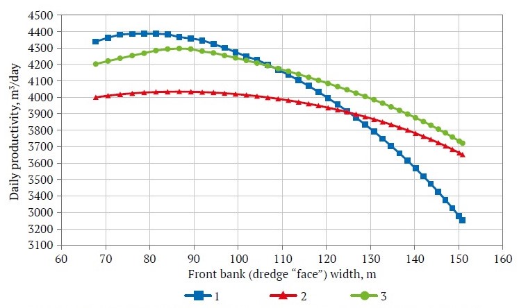
Fig. 1. Daily productivity of a 380-liter dredge as a function of front bank width:
1 – according to the technique of V. A. Kudryashev; 2 – according to the technique of V. G. Leshkov; 3 – according to the technique of S. M. Shorokhov
To further investigate the effect of stripping on the optimal front bank width, we use the most wellknown and widely used design technique developed by V. G. Leshkov [6], in which the daily productivity of a dredge is determined using the following expression:
Qday = (3600vlHaTR sin β1)/(0,0175KlRavg + 30vl(t1 + Klt2)), (1)
where vl is speed of lateral dredge movement along a front bank, m/s; Н is a placer deposit thickness, extracted by the buckets, m; a is a value of moving (step) of a dredge per a front bank, m; Т is dredge operating time per day, h; Ravg is average dredge digging radius when mining a placer deposit of Н thick, m; β1 is half the maneuvering angle of a dredge, degrees; Kl = Н/h is number of rock layers extracted by the buckets during layer-by-layer mining of one front bank; t1 is time required for one step, min; t2 is downtime of a dredge in front bank node points when advancing to a lower rock layer extraction, min; 0.0175 is digital coefficient for converting degrees to radians.
The works of V. G. Leshkov [6] describe a method for calculating the optimal front bank width, which takes into account the thickness of a sand to be dredged and the design parameters of the mining equipment. The most advantageous width of a single front bank is established based on the conditions of maximum dredge productivity in terms of rock mass and is determined by the most advantageous maneuvering angle. The calculation formula is as follows:
βma = 47,8√[1000vlh(t1 + Ht2)/h]. (2)
The most advantageous width of a single front bank, m, is calculated using the following equation:
Bma = 2Ravg sin β1. (3)
The method proposed by V. G. Leshkov for calculating the most advantageous front bank width takes into account the main parameters of equipment operation and the nature of a productive layer, but does not assume the presence and scope of overburden. Therefore, it is necessary to predict how the most advantageous (optimal) front bank width will change, when taking into account the work involved in extracting and transporting peat.
1 Kudryashev V. A. Some issues of the theory and technology of deep placer deposits development using dredging method. [Abstr. Dr. Sci. (Eng.) Diss.] Мoscow: MSTU Publ.; 1975. 42 p. (In Russ.)
Research tasks and objectives
The main objective of the research was to determine an optimal front bank width depending on the thickness of a mineral deposit and overburden. To achieve this goal, it is necessary to establish the influence of peat thickness on the costs of mineral extraction, determine the front bank parameters, which ensure minimum costs for a placer deposit development, and improve the method for calculating the most advantageous width of a front bank (a dredge run) for the development of wide placer deposits.
Research techniques
Graphical and technical-economic calculation methods were used to solve the tasks set. The influence of stripping on the optimal front bank width was assessed based on the calculation of the costs of mineral extraction depending on the parameters of the front bank, peat thickness, and the method used for the peat extraction and stockpiling.
For peat thickness of up to 6 m, the calculations were performed for bulldozer stripping method, and for the thickness more than 6 m, the calculations provided for direct dumping method with the use of draglines. According to approved stripping flow sheets, peat dumps are placed on one side of a placer deposit or into worked-out space left from the previous dredging run. Transport technique for stripping with the use of a combination of excavators and dump trucks was not considered, as its high cost (2–3 times higher than direct dumping and bulldozer methods) means that it is practically never used in dredging mining.
To determine the costs of stripping and mining operations under different mining parameters of a placer deposit and flow sheets used, the dependencies of mining equipment productivity and the volume of earthwork on a front bank width were found. The productivity of bulldozers was determined based on the transportation distance and the height of the dumps, while the volume of excavation work was calculated taking into account changes in the rehandling coefficient. The costs of stripping and mining operations were determined based on the cost per machine-hour of the equipment used, its productivity, and the scope of stripping.
Findings
The influence of stripping technique on an optimal front bank width was assessed based on the calculation of the costs of stripping (in Rubles per cubic meter of sand extracted) and the costs of dredging. Minimum costs for stripping and mining operations are achieved with maximum productivity of the equipment used.
Based on a dredge's productivity, the costs of extracting and processing of one cubic meter of sand were calculated. Fig. 2 shows curves of cost of sand extraction as a function of a front bank width at three productive layer thicknesses of 10, 20, and 28 m.
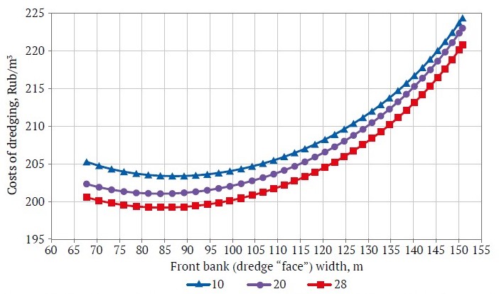
Fig. 2. Curves of cost of dredging as a function of a front bank width for a 380-liter dredge at three productive layer thicknesses of 10, 20, and 28 m
As can be seen from Fig. 2, the minimum costs were achieved at a front bank width of 70–100 m.
In order to assess the influence of stripping on the total costs of extracting one cubic meter of sand, the productivity of bulldozers was calculated when using front bank width values of 50–155 m and varying sand thickness (from 6 to 28 m). The thickness of sand also affects the front bank width, as the width increases at the top. For peat thickness of 2–6 m, the relationship between the productivity and costs of stripping using bulldozers (with a power of 350–400 kW) and the front bank width was established.
The bulldozer's productivity for each case was determined based on the distance of peat transportation. As the front bank width increases, the distance of transportation and the parameters of the bulldozer dump (height, required capacity) increase, while the productivity of the stripping equipment decreases and, as a result, the costs of sand extraction increase.
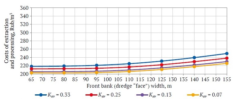
Fig. 3. Cost of extraction and processing of a mineral as a function of front bank width at a peat thickness of 2 m and a stripping ratio Kstr = 0.07–0.33
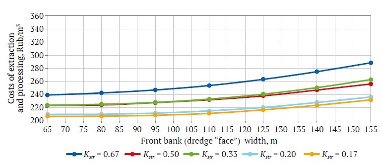
Fig. 4. Cost of extraction and processing of a mineral as a function of front bank width at a peat thickness of 4 m and a stripping ratio Kstr = 0.17–0.67
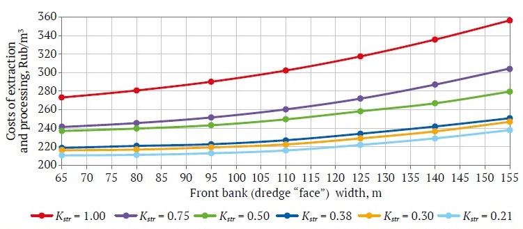
Fig. 5. Cost of extraction and processing of a mineral as a function of front bank width at a peat thickness of 6 m and a stripping ratio Kstr = 0.21–1.00
The cost of extraction and processing of one cubic meter of sand (taking into account the costs of stripping by bulldozers) as a function of front bank width are shown in Figs. 3–5. Table 1 shows the results of calculating the costs of extraction at different values of peat and sand thicknesses and front bank width.
Table 1
Costs of extraction and processing of sand using a dredge, including stripping by bulldozers, Rub/m3
Thickness, m | Costs of extraction and processing of a mineral at different values of front bank (dredge “face”) peat sand width, m | ||||||||
| peat | sand | ||||||||
Tp | Ts | 50 | 65 | 80 | 95 | 110 | 125 | 140 | 155 |
2 | 6 | 217.8 | 218.2 | 218.9 | 220.5 | 227.1 | 231.1 | 239.6 | 249.5 |
8 | 211.9 | 212.3 | 212.7 | 213.4 | 219.1 | 222.4 | 229.8 | 238.2 | |
12 | 212.1 | 211.9 | 211.9 | 212.7 | 218.5 | 221.6 | 229.1 | 238.0 | |
16 | 205.8 | 205.6 | 205.7 | 206.3 | 212.0 | 214.8 | 221.9 | 230.0 | |
20 | 205.2 | 204.9 | 204.7 | 205.4 | 211.1 | 213.6 | 220.5 | 228.9 | |
24 | 203.1 | 202.7 | 202.4 | 202.9 | 208.4 | 210.9 | 217.8 | 225.6 | |
28 | 202.7 | 202.3 | 202.1 | 202.5 | 207.8 | 210.3 | 217.1 | 225.0 | |
4 | 6 | 236.8 | 239.4 | 242.6 | 246.8 | 256.1 | 263.2 | 274.9 | 288.4 |
8 | 222.1 | 223.5 | 224.2 | 227.5 | 234.4 | 238.1 | 247.0 | 256.2 | |
12 | 222.7 | 223.8 | 225.3 | 227.9 | 235.5 | 240.7 | 250.6 | 262.8 | |
16 | 211.5 | 211.5 | 211.9 | 213.3 | 219.7 | 223.3 | 230.4 | 239.7 | |
20 | 209.6 | 209.9 | 210.2 | 211.4 | 217.7 | 220.4 | 228.0 | 236.4 | |
24 | 206.9 | 207.0 | 207.2 | 208.2 | 213.8 | 216.8 | 223.8 | 231.9 | |
28 | 206.2 | 206.0 | 206.1 | 206.9 | 212.5 | 215.4 | 222.3 | 230.9 | |
6 | 6 | 266.5 | 273.1 | 280.7 | 289.8 | 304.5 | 317.4 | 335.6 | 356.3 |
8 | 235.1 | 237.0 | 239.5 | 242.8 | 251.8 | 258.2 | 266.8 | 279.4 | |
12 | 237.7 | 241.2 | 245.4 | 251.2 | 262.5 | 271.8 | 287.0 | 304.4 | |
16 | 217.8 | 218.6 | 220.7 | 222.1 | 229.3 | 233.8 | 241.7 | 250.6 | |
20 | 214.7 | 216.0 | 216.8 | 218.7 | 224.7 | 228.8 | 236.4 | 246.8 | |
24 | 211.9 | 212.4 | 213.1 | 213.9 | 220.5 | 223.4 | 231.5 | 240.6 | |
28 | 210.3 | 210.6 | 211.1 | 212.4 | 218.2 | 221.8 | 228.9 | 237.7 | |
Figs. 3–5 show that when a front bank width exceeds 95 m, the costs of mineral extraction and processing sharply increase. This confirms that when designing dredging operations and determining an optimal front bank width, the parameters of stripping must be taken into account.
Table 2 shows the data for calculating an optimal front bank width using formula (2) and the indicators identified taking into account the conduct of stripping operations. The correction factor was calculated, which is proposed to be used in formula (2) when calculating the optimal front bank width for a 380 l dredge under similar placer parameters.
Table 2
Optimal front bank width taking into account stripping Wstr and not taking into account stripping W with the use of bulldozers
Tp | Ts | Kstr | W | Wstr | Difference, % | Recommended correction factor |
2 | 6 | 0.33 | 100.9 | 100.0 | 0.9 | 1.00 |
8 | 0.25 | |||||
12 | 0.17 | |||||
16 | 0.13 | 91.2 | 95.0 | - | 1.00 | |
20 | 0.10 | |||||
24 | 0.08 | 84.5 | 95.0 | - | 1.00 | |
28 | 0.07 | |||||
4 | 6 | 0.67 | 100.9 | 80.0 | 20.7 | 0.79 |
8 | 0.50 | |||||
12 | 0.33 | |||||
16 | 0.25 | 91.2 | 80.0 | 12.3 | 0.88 | |
20 | 0.20 | |||||
24 | 0.17 | 84.5 | 80.0 | 5.3 | 0.95 | |
28 | 0.14 | |||||
6 | 6 | 1.00 | 100.9 | 65.0 | 35.6 | 0.64 |
8 | 0.75 | |||||
12 | 0.50 | |||||
16 | 0.38 | 91.2 | 65.0 | 28.7 | 0.71 | |
20 | 0.30 | |||||
24 | 0.25 | 84.5 | 65.0 | 23.1 | 0.77 |
Notes: Tp is peat thickness, m; Ts is sand thickness, m; Kstr is stripping ratio, m3/m3; Wstr is optimal front bank width taking into account stripping, m; W is optimal front bank width without taking into account stripping, m.
As the thickness of peat increases, the cost of extracting minerals rises, while an optimal front bank width gradually decreases. As can be seen from Table 2, the difference between the calculated values of the optimal front bank width without and with bulldozer stripping ranges from 0 to 35.6%. The graphical representation of the correction factor variation depending on certain parameters of a placer deposit (peat thickness and stripping ratio) is shown in Fig. 6.
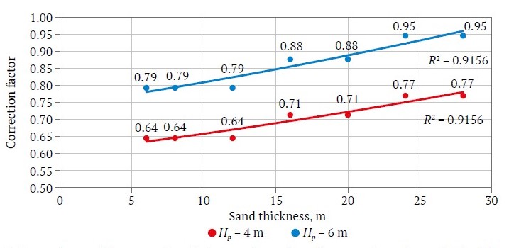
Fig. 6. Dependence of the correction factor on placer deposit parameters when using bulldozers in stripping work and peat thicknesses of 4 and 6 m
When dredging developing placers with peat thicknesses exceeding 5–6 m, the feasibility of using bulldozers for stripping decreases; instead, a direct dumping technique is applied.
When studying the influence of a front bank width on the cost of dredging with the use of direct dumping technique, 140 flow sheets for stripping using an ESh 20/90 dragline were analyzed, in which the thicknesses of the overburden (5–20 m), sand (6–28 m), and the front bank width (50–140 m) varied. For each flow sheet, the rehandling coefficients were calculated using a dummy unit-load method and are presented in Table 3.
Table 3
Rehandling coefficients, m3/m3, for different flow sheets of stripping with the use of a ESh 20/90 dragline
Overburden thickness, m | Sand thickness, m | Rehandling coefficient for different front bank (dredge “face”) width, m | ||||
50 | 65 | 90 | 120 | 140 | ||
5 | 6 | 0 | 0 | 0 | 0 | 0 |
8 | 0 | 0 | 0 | 0 | 0.08 | |
12 | 0 | 0 | 0 | 0 | 0.14 | |
16 | 0 | 0 | 0 | 0.05 | 0.24 | |
20 | 0 | 0 | 0 | 0.13 | 0.29 | |
24 | 0 | 0 | 0 | 0.29 | 0.37 | |
28 | 0 | 0 | 0 | 0.33 | 0.4 | |
10 | 6 | 0 | 0 | 0 | 0 | 0.17 |
8 | 0 | 0 | 0 | 0 | 0.23 | |
12 | 0 | 0 | 0 | 0.08 | 0.27 | |
16 | 0 | 0 | 0 | 0.23 | 0.37 | |
20 | 0 | 0 | 0 | 0.32 | 0.43 | |
24 | 0 | 0.08 | 0.17 | 0.41 | 0.49 | |
28 | 0 | 0.1 | 0.25 | 0.44 | 0.51 | |
15 | 6 | 0 | 0 | 0 | 0.05 | 0.2 |
8 | 0 | 0 | 0.05 | 0.1 | 0.25 | |
12 | 0 | 0 | 0.06 | 0.14 | 0.31 | |
16 | 0 | 0 | 0.12 | 0.25 | 0.46 | |
20 | 0 | 0.04 | 0.2 | 0.36 | 0.58 | |
24 | 0.04 | 0.09 | 0.37 | 0.48 | 0.76 | |
28 | 0.08 | 0.11 | 0.4 | 0.6 | 0.85 | |
20 | 6 | 0 | 0 | 0.13 | 0.19 | 0.36 |
8 | 0 | 0 | 0.19 | 0.26 | 0.43 | |
12 | 0 | 0.09 | 0.3 | 0.31 | 0.47 | |
16 | 0.08 | 0.13 | 0.32 | 0.48 | 0.57 | |
20 | 0.11 | 0.19 | 0.43 | 0.51 | 0.69 | |
24 | 0.15 | 0.21 | 0.54 | 0.56 | 1.08 | |
28 | 0.17 | 0.23 | 0.58 | 0.69 | 1.51 | |
Table 4
Costs of extraction and processing of sand using direct dumping technique in stripping work, Rub/m3
Peat thickness, m | Sand thickness, m | Front bank (dredge “face”) width, m | ||||
50 | 65 | 90 | 120 | 140 | ||
5 | 6 | 221.9 | 221.0 | 220.1 | 229.1 | 237.6 |
8 | 217.8 | 216.8 | 216.0 | 223.9 | 233.2 | |
12 | 213.6 | 212.6 | 211.8 | 218.7 | 228.1 | |
16 | 208.6 | 207.8 | 207.5 | 214.6 | 224.4 | |
20 | 207.3 | 206.6 | 206.3 | 213.4 | 222.8 | |
24 | 204.7 | 204.0 | 204.6 | 210.8 | 219.7 | |
28 | 204.1 | 203.4 | 203.9 | 210.0 | 218.8 | |
10 | 6 | 238.6 | 237.6 | 236.8 | 249.9 | 263.2 |
8 | 230.3 | 229.3 | 228.5 | 239.5 | 252.9 | |
12 | 221.9 | 221.0 | 224.3 | 230.2 | 241.4 | |
16 | 214.8 | 217.2 | 216.9 | 224.6 | 234.9 | |
20 | 212.3 | 214.1 | 213.8 | 221.8 | 231.5 | |
24 | 210.7 | 211.1 | 211.5 | 217.9 | 227.1 | |
28 | 209.3 | 209.6 | 209.9 | 216.2 | 225.2 | |
15 | 6 | 255.3 | 254.3 | 266.0 | 272.9 | 287.7 |
8 | 242.8 | 241.8 | 251.9 | 258.3 | 271.6 | |
12 | 235.8 | 235.6 | 238.8 | 242.5 | 254.6 | |
16 | 225.7 | 225.0 | 226.6 | 234.0 | 246.1 | |
20 | 221.1 | 220.8 | 222.6 | 229.9 | 241.4 | |
24 | 216.6 | 216.4 | 219.0 | 225.3 | 236.9 | |
28 | 214.7 | 214.2 | 216.5 | 223.4 | 234.3 | |
20 | 6 | 271.9 | 287.6 | 294.2 | 302.3 | 320.5 |
8 | 255.3 | 266.8 | 274.1 | 281.8 | 297.5 | |
12 | 246.9 | 248.5 | 253.6 | 258.7 | 271.7 | |
16 | 235.3 | 235.6 | 239.3 | 248.0 | 258.7 | |
20 | 229.2 | 229.8 | 233.6 | 240.2 | 252.0 | |
24 | 223.5 | 223.6 | 227.9 | 233.3 | 249.3 | |
28 | 220.0 | 220.4 | 224.3 | 230.8 | 249.4 | |
The data in Table 3 show that at the highest values of the front bank width, the rehandling coefficient for the stripping dragline is maximal; therefore, the costs of stripping in such conditions will be higher.
The cost of stripping and dredging has been calculated for each option. Table 4 shows the results of calculating the extraction costs when using direct dumping technique for stripping.
By analogy with the analysis of the bulldozer method of stripping (peat removal) (see above), the indicators calculated without taking into account stripping and with its taking into account when using direct dumping technique were compared (Table 5).
Table 5
Optimal front bank (dredge “face”) width taking into account stripping Wstr, and not taking into account stripping W, when using direct dumping technique
Tp | Ts | Kstr | W | Wstr | Difference | % | Correction factor |
5 | 6 | 0.83 | 100.9 | 100.0 | 0.9 | 0.9 | 0.99 |
8 | 0.63 | ||||||
12 | 0.42 | ||||||
16 | 0.31 | 91.2 | 90.0 | 1.2 | 1.3 | 0.99 | |
20 | 0.25 | ||||||
24 | 0.21 | 84.5 | 85.0 | −0.5 | −0.6 | 1.01 | |
28 | 0.18 | ||||||
10 | 6 | 1.67 | 100.9 | 90.0 | 10.9 | 10.8 | 0.89 |
8 | 1.25 | ||||||
12 | 0.83 | ||||||
16 | 0.63 | 91.2 | 90.0 | 1.2 | 1.3 | 0.99 | |
20 | 0.50 | ||||||
24 | 0.42 | 84.5 | 85.0 | −0.5 | −0.6 | 1.01 | |
28 | 0.36 | ||||||
15 | 6 | 2.50 | 100.9 | 65.0 | 35.9 | 35.6 | 0.64 |
8 | 1.88 | ||||||
12 | 1.25 | ||||||
16 | 0.94 | 91.2 | 65.0 | 26.2 | 28.7 | 0.71 | |
20 | 0.75 | ||||||
24 | 0.63 | 84.5 | 65.0 | 19.5 | 23.1 | 0.77 | |
28 | 0.54 | ||||||
20 | 6 | 3.33 | 100.9 | 50.0 | 50.9 | 50.5 | 0.50 |
8 | 2.50 | ||||||
12 | 1.67 | ||||||
16 | 1.25 | 91.2 | 50.0 | 41.2 | 45.2 | 0.55 | |
20 | 1.00 | ||||||
24 | 0.83 | 84.5 | 50.0 | 34.5 | 40.8 | 0.59 |
Notes: Tp is peat thickness, m; Ts is sand thickness, m; Kstr is stripping ratio, m3/m3; Wstr is optimal front bank width taking into account stripping, m; W is optimal front bank width without taking into account stripping, m.
As can be seen from Table 5, the difference between the two calculation options results varies from 1.3 to 50.5%. With high peat thickness, consideration of stripping when calculating the optimal front bank width has a more significant effect.
Graphical dependencies of the correction factor on the parameters of a placer deposit when using direct dumping in stripping work are shown in Fig. 7.
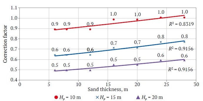
Fig. 7. Dependence of the correction factor on placer deposit parameters when using direct dumping in stripping work and peat thicknesses of 10, 15, 20 m
Thus, when calculating an optimal front bank width, it is proposed to take into account a correction factor, the values of which are given in Table 2 (for bulldozer stripping) and Table 5 (for direct dumping stripping). The formula will assume the form of:
Bma = Kcorr[2R sin (βma/2)], (4)
where Kcorr is a correction factor that takes into account the parameters of a placer deposit and the equipment used in stripping.
Conclusions
1. The presence of overburden on dredging sites has a significant impact on the most advantageous front bank width, which, depending on the thickness of peat, is reduced by 1.05–1.5 times (by 5–50%) relative to the recommended values.
2. It is most important to take into account stripping when determining the optimal front bank width for a 380-liter dredge at peat thickness exceeding 2 m (when using bulldozers) and peat thickness exceeding 5 m (when using direct dumping with ESh 10/70, ESh 20/90 draglines).
3. With an increase in peat thickness and the stripping ratio, the optimal front bank width is significantly reduced and should be taken as equal to the minimum possible value for the bulldozer method of stripping (peat overburden removal) at a peat thickness of more than 6 m, and for direct dumping technique, more than 15 m.
4. It is recommended to calculate the optimal front bank width using the formula developed by V. G. Leshkov with the use of the proposed correction factor. When using less powerful equipment for stripping, such as bulldozers with a power of 200–250 kW or ESh 6/45 dragline excavators, the proposed correction factors will be significantly reduced.
References
1. Nafikov R. Z., Kislyakov V. E. Technology of dredging development of placer deposits in the conditions of the Far North. Krasnoyarsk: Siberian Federal University Publ.; 2021. 184 p. (In Russ.)
2. Dorosh E. A., Talgamer B. L. Analysis of the mineral resource base of gold mining in the Lena gold-bearing district and substantiation of the development directions of placer mining methods. Earth sciences and subsoil use. 2022;45(3):222–234. (In Russ.) https://doi.org/10.21285/2686-9993-2022-45-3-222-234
3. Van-Van-E A. P. Resource base of natural and man-made gold placer deposits. Moscow: Gornaya Kniga Publ.; 2010. 268 p. (In Russ.)
4. Bortnikov N. S., Volkov A. V., Lalomov A. V. et al. The role of placer deposits in ensuring the reproduction of the mineral resource base of scarce types of strategic mineral raw materials in Russia at the present stage. Russian Journal of Earth Sciences. 2024;(1):1–16. (In Russ.) https://doi.org/10.2205/2024ES000897
5. Dudinsky F. V., Nechaev K. B., Kostromitinov K. N. The effectiveness of the combined development of deep alluvial deposits. Izvestiya Vysshikh Uchebnykh Zavedenii. Gornyi zhurnal. 2012;(5):4–9. (In Russ.)
6. Leshkov V. G. Theory and practice of placer mining using multi-bucket dredges. Moscow: Nedra Publ.; 1980. 352 p. (In Russ.)
7. Okoyen E., Raimi M. O., Omidiji A. O., Ebuete A. W. Governing the environmental impact of dredging: Consequences for marine biodiversity in the Niger delta region of Nigeria. Insights Mining Science and Technology. 2020;2(3):76–84. https://doi.org/10.19080/IMST.2020.02.555586
8. Marrugo-Negrete J., Pinedo-Hernandez J., Marrugo-Madrid S. et al. Evaluating ecological risks and metal bioavailability in post-dredging sediments of a wetland affected by artisanal gold mining. Science of the Total Environment. 2024;955:176309. https://doi.org/10.1016/j.scitotenv.2024.176309
9. Mantey J., Nyarko K. B., Owusu-Nimo F. et al. Influence of illegal artisanal small-scale gold mining operations (galamsey) on oil and grease (O/G) concentrations in three hotspot assemblies of Western Region, Ghana. Environmental Pollution. 2020;263(Part B):114251. https://doi.org/10.1016/j.envpol.2020.114251
10. Talgamer B. L., Dudinskiy F. V., Murzin N. V. Assessment of conditions and experience of technogenic placer dredging. In: IOP Conference Series: Earth and Environmental Science, Volume 408, 2nd International Scientific Conference «Sustainable and Efficient Use of Energy, Water and Natural Resources. 16–20 September 2019, Irkutsk Region, Russian Federation. 2020;408(1):012065. https://doi.org/10.1088/1755-1315/408/1/012065
11. Timsina S., Hardy N. G., Woodbury D. J. et al. Tropical surface gold mining: A review of ecological impacts and restoration strategies. Land Degradation & Development. 2022;33(18):3661–3674. https://doi.org/10.1002/ldr.4430
12. Queiroz J., Gasparinetti P., Bakker L. B. et al. Socioeconomic cost of dredge boat gold mining in the Tapajós basin, eastern Amazon. Resources Policy. 2022;79(2):103102 https://doi.org/10.1016/j.resourpol.2022.103102
13. Cano-Londoño N. A., Capaz R. S., Hasenstab C. et al. Life cycle impacts assessment of two gold extraction systems in Colombia: open-pit and alluvial mining. The International Journal of Life Cycle Assessment. 2023;28(4):380–397. https://doi.org/10.1007/s11367-023-02141-5
14. Davies P., Lawrence S., Turnbull J. et al. Mining modification of river systems: A case study from the Australian gold rush. Geoarchaeology. 2019;1–16. https://doi.org/10.1002/gea.21775
15. Murzin N. V., Dudinskiy F. V., Talgamer B. L. Evaluation of non-productive time when calculating pile-type dredge performance. Mining Industry Journal. 2021;(2):120–126. (In Russ.) https://doi.org/10.30686/1609-9192-2021-2-120-126
16. Mirzekhanov G. S., Mirzekhanova Z. G. Forward appraisal of potential gold content of dredge and sluice tailings dumps at placers in Russia’s Far East. Journal of Mining Science. 2020;56(2):259–267. https://doi.org/10.1134/S1062739120026733
17. Helmons R., de Wit L., de Stigter H., Spearman J. Dispersion of benthic plumes in deep-sea mining: What lessons can be learned from dredging? Frontiers in Earth Science. 2022;10. https://doi.org/10.3389/feart.2022.868701
18. Torres C., Verschoor G. Re-imagining environmental governance: Gold dredge mining vs Territorial Health in the Colombian Amazon. Geoforum. 2020;117(4):124–133. https://doi.org/10.1016/j.geoforum.2020.09.013
19. Shorokhov S. M. Technology and complex mechanization of development of placer deposits. Moscow: Nedra Publ.; 1973. 795 p. (In Russ.)
About the Authors
B. L. TalgamerRussian Federation
Boris L. Talgamer – Dr. Sci. (Eng.), Professor, Head of the Department of Mineral Deposit Development
Irkutsk
Scopus ID 57196258850
I. A. Meshkov
Russian Federation
Ivan A. Meshkov – PhD-Student, Department of Mineral Deposit Development, Research Engineer
Irkutsk
N. V. Murzin
Russian Federation
Nikolay V. Murzin – Cand. Sci. (Eng.), Associate Professor of the Department of Mineral Deposit Development
Irkutsk
Scopus ID 57217845755
Yu. G. Roslavtseva
Russian Federation
Yulia G. Roslavtseva – Cand. Sci. (Eng.), Associate Professor of the Department of Mineral Deposit Development
Irkutsk
Scopus ID 57208126909
Review
For citations:
Talgamer B.L., Meshkov I.A., Murzin N.V., Roslavtseva Yu.G. Justification of the optimal width of a front bank. Mining Science and Technology (Russia). 2025;10(2):99-108. https://doi.org/10.17073/2500-0632-2024-11-332


