Contents
Scroll to:
https://doi.org/10.17073/2500-0632-2025-07-1104
Scroll to:
Comprehensive consideration of the geomechanical and structural characteristics of the rock mass is a prerequisite for ensuring the safety and efficiency of underground mining operations. The key parameters that must be incorporated into computational models include the physical, mechanical and strength properties of rocks, their degree of fracturing, as well as the initial and mining-induced stress state of the rock mass. This study investigates geomechanical criteria for determining support parameters of development workings under conditions of plastic deformation. The methodological framework is based on a combination of theoretical analysis, finite element numerical modeling using the RS2 software package (Rocscience), and generalization of experimental data on the properties of host rocks. This approach enabled a detailed analysis of the stress-strain state of the rock mass at various stages of mining operations, including the roadway junction where a new roadway is driven from an existing excavation and its subsequent development. The modeling results established the spatial boundaries of deformation zones: the depth of developed inelastic deformation reaches 0.6–0.7 m from the excavation boundary, while the elastoplastic deformation zone extends to 1.8–1.9 m. Stress analysis showed that in the abutment pressure zone ahead of the excavation face, stresses reach values of 20.48 MPa, which is about 25% higher than the in-situ stress level at a depth of 600 m. Analysis of the Factor of Safety (FoS) revealed local zones with FoS < 1 in the junction zone, indicating the need for reinforcement of the support system. The results provide a scientifically substantiated basis for predicting the geomechanical state of the rock mass and for selecting rational support parameters, thereby improving excavation stability, reducing maintenance requirements, and enhancing industrial safety in underground coal mining.
Demin V.F., Valiev N.G., Akhmatnurov D.R., Mussin R.A., Zamaliyev N.M. Formation of inelastic deformation zones based on numerical modeling. Mining Science and Technology (Russia). 2026;11(1):90-102. https://doi.org/10.17073/2500-0632-2025-07-1104
To ensure efficient mineral deposit development, it is necessary to account for the physical, mechanical and strength properties of rocks, the degree of fracturing, and the stress state of the rock mass. This makes it possible to identify deformation patterns and zones of increased stress that affect the stability of mine workings and working conditions [1, 2].
The roof, ribs, and floor rocks of development workings in coal mines of the Karaganda coal basin are characterized by relatively low uniaxial compressive strength, failing in the range of 20–37 MPa, and are classified as weak and unstable rocks. When exposed over distances exceeding one meter, they tend to collapse and are also prone to slaking and floor heave.
Since the stability of underground mine workings remains one of the most critical factors determining the operational efficiency of coal mines in the Karaganda basin of the Republic of Kazakhstan, it is necessary to conduct applied scientific studies aimed at determining support parameters in zones of roof arch formation and performing predictive geomechanical assessment of the deformation state of the host rock mass in coal seams, taking into account their stress–strain conditions [3, 4].
At present, the development of this scientific field in the coal industry of Kazakhstan is associated with assessing the formation of inelastic deformation zones using numerical modeling [5, 6]. The practical value of such research lies in the implementation of its results for testing advanced geotechnical solutions in coal mines of the Karaganda basin.
The aim of this study is to provide a geomechanical justification of support parameters for mine workings based on the investigation of the stress–strain state of near-excavation zones of the coal-bearing rock mass under various operating conditions.
The main objectives are:
The concept underlying this study is that geomechanical forecasting of the development of inelastic deformation and stress redistribution zones in mining-disturbed rock masses surrounding an excavation can serve as the basis for determining the technological parameters of support systems for development workings, thereby ensuring their stability.
This study presents an integrated methodology that combines geomechanical characterization of the rock mass, prediction of deformation for various support schemes depending on seam depth, geometry, and lithological properties, and numerical modeling. The application of deformation-state assessment for stabilizing excavation boundaries in coal mines will reduce repair volumes and significantly improve operational safety, efficiency, and the timeliness of longwall panel preparation.
The present study relies on numerical methods for modeling support technologies aimed at stabilizing the coal-bearing host rock mass surrounding mine workings, with particular emphasis on the stress–strain state under rock pressure conditions.
The methodological approach involves constructing a computational model of the unstable rock volume separated from the rock mass by weakening contacts, which represents the spatial configuration of the excavation, surrounding rock layers, and coal seam.
One of the most common manifestations of rock pressure is the failure of the rock mass surrounding an underground excavation [7, 8]. Such failure may extend over significant areas of the rock mass, causing the collapse of rock fragments into the excavation under their own weight. When the failure zone is smaller, rock pressure manifests itself in the spalling of individual rock blocks. Another form of manifestation is the deformation of the excavation boundary during operation. In most cases, both forms occur simultaneously, with the most hazardous being dynamic manifestations such as rock bursts, sudden outbursts, and brittle rock spalling [9, 10]. Rock mass failure near underground structures occurs when a specific combination of stress–strain parameters reaches a critical level1 [2, 11].
Stresses in the host rock mass surrounding the excavation [12, 13] that exceed the creep threshold gradually decrease over time due to the development of plastic deformation in the rocks. As stresses decrease, the rate of rock deformation also declines, which in turn reduces the rate of displacement of the excavation boundary. Conversely, an increase in stresses initiates a new phase of displacement.
Within the inelastic deformation zone, the integrity of the rock mass is disrupted, resulting in microdefects that develop into macrofractures. The growth of such deformation (dilatancy) leads to an increase in rock volume, which may exceed the displacements caused by elastic deformation by an order of magnitude. This phenomenon constitutes the main cause of rock displacement in the near-excavation zone of mine workings under active rock pressure conditions2 [14].
Therefore, it is essential to determine the extent of inelastic deformation in rocks at the limit state, taking into account the size of the inelastic deformation zone and the degree of rock loosening in the post-failure region [15].
1 Zhurov V. V. Improvement of the methodology for calculating support parameters of mine workings taking into account mining and technological factors. [Diss. ... Cand. Sci. (Eng.) ]. Karaganda: Karaganda State Technical University; 2010. 115 p.
2 Demin V. F., Sitnikov R. S., Steflyuk Yu. Yu., et al. Device for supporting excavation contours in unstable rocks. Patent 31419, Republic of Kazakhstan; IPC E21D 21/00. Published August 15, 2016, Bulletin No. 9.
The mining industry of Kazakhstan is one of the leading sectors of the national economy. Intensive exploitation of the mineral resource base presents mining enterprises with a number of complex challenges related to ensuring the stability and safety of underground excavations. Of particular importance is the monitoring of rock mass displacements around mine workings, which becomes critically significant when deposits are mined at greater depths, where rock pressure increases substantially [16, 17].
The geological conditions of Kazakhstan are characterized by considerable diversity of rock mass types, including coal, iron ore, polymetallic, and other deposits. The Karaganda coal basin, one of the largest in the country, is distinguished by complex seam structures, significant mining depths, and high geomechanical loads. These conditions require the application of modern modeling methods to assess the stress–strain state of the rock mass. These issues become especially important in the context of increasing requirements for mining safety and the need to minimize risks associated with failure of the near-contour rocks surrounding underground excavations.
Typical manifestations of rock pressure around an advancing excavation include the abutment pressure zone, the stress concentration zone ahead of the face that develops into a fractured rock zone, and zones of compression and crushing of the rock mass in the immediate vicinity of the excavation face.
Driving an underground excavation disturbs the equilibrium state of the rock mass and causes a redistribution of stresses in the surrounding rock. In this case, the stress intensity at the excavation boundary is significantly higher than in the undisturbed rock mass. Elevated stresses at the excavation boundary lead to the formation of an inelastic deformation zone around it [16, 17]. The structure of this zone and the nature of rock deformation within it depend on several factors, including the depth of the excavation, the rock type and its physical, mechanical and technological properties, the size of the excavation, the type and characteristics of the support system, and the dip angle of the host rocks. Manifestations of rock pressure observed in driven workings include displacements of the rock mass in the near-excavation zone [7].
The primary focus of this study is the determination of displacements of the excavation boundary based on experimentally obtained data on rock properties and the stress–strain state of the rock mass.
Several studies have proposed recommendations for reducing the rock mass loosening coefficient associated with dilatancy, which can be achieved by adjusting support parameters, excavation geometry, and controlling the rate of rock deformation.
To achieve the research objective, a comprehensive research methodology was applied, combining theoretical analysis, numerical modeling, and experimental investigations. Such an approach is necessitated by the complex nonlinear nature of deformation in coal-bearing rock masses, where the stress–strain state of the near-excavation zone is governed by the combined influence of mining conditions, physical and mechanical rock properties, and support system parameters.
Numerical modeling was used to predict excavation boundary deformation and to analyze stress redistribution, theoretical methods were applied to generalize and interpret the identified patterns, and experimental investigations were carried out to verify the calculated results and refine the initial parameters of the model.
To establish geomechanical patterns occurring in development workings driven in coal seams, analytical studies were performed to determine roof deformation along the axis of the development working.
The analysis considers the features of stress redistribution and the formation of deformation zones in the rock mass depending on the properties of the host rocks and the parameters of the excavation. The analysis was performed on the basis of numerical modeling that accounts for the geomechanical characteristics of the rock mass and the support schemes in order to identify patterns in the evolution of the stress–strain state and potential zones of instability.
The following mathematical model describes manifestations of rock pressure around a driven excavation associated with rock mass displacements in the near-excavation zone. The total displacement of the rock mass in the excavation Utot is composed of elastic U1 and inelastic U2 components:
Utot = U1 + U2. (1)
Elastic deformation is determined by the following equations [7]:
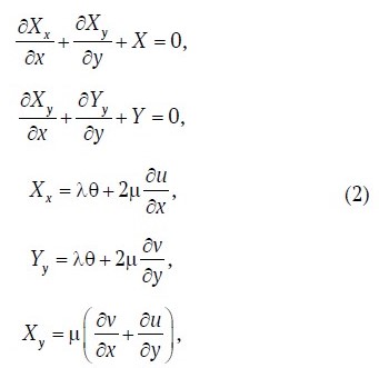
where Х, У, Хх, Уу are the displacement vectors and their projections on the coordinate axes; μ is Poisson’s ratio; ν is the viscosity coefficient, N/m²; u is the deformation rate, m/day; λ is the lateral pressure coefficient; r, θ are the polar coordinates of the points.
Inelastic deformation of rocks in the plastic failure zone is determined by the following equation [8]:

where Sd is the area of the inelastic deformation zone, m²; Pexc is the excavation perimeter, m; Kl is the rock mass loosening coefficient in the post-failure deformation zone.
Numerical modeling of the stress–strain state of the rock mass was carried out using the RS2 (Rocscience) software package, which implements the finite element method (FEM). The choice of this software is determined by its specialization for geomechanical analysis of underground excavations, the ability to account for complex excavation geometry, layered rock mass structure, nonlinear deformation behavior of rocks, and the implementation of various strength criteria and boundary conditions typical of underground mining conditions. The finite element method implemented in RS2 allows adequate representation of stress redistribution and deformation development in the near-excavation zones of the rock mass, which is critically important for analyzing excavation stability and substantiating support parameters.
The modeling procedure included the following stages:
To provide a more comprehensive analysis of the formation mechanism of inelastic deformation zones around a mine excavation during its advance, numerical modeling was performed using the RS2 software package. In this study, a model was developed that takes into account the geological conditions at the roadway junction, followed by the driving of the excavation along the coal seam at a depth of 600 m below the surface.
The model conditions included the rocks of the excavation floor, represented by argillites and siltstones, as well as the roof of the coal seam, composed of siltstones and sandstones. Particular attention was given to the analysis of the stress–strain state of the rock mass, including the identification of zones of inelastic deformation that arise as a result of changes in rock pressure and the interaction between the rock mass and the excavation boundary. The overall numerical model is shown in Fig. 1.

Fig. 1. Numerical model of excavation development
The model was structured in stages, which made it possible to analyze in detail the evolution of the stress–strain state of the rock mass at each stage of excavation development.
The initial stage of modeling involves the excavation of the first roadway, which serves as the junction point from which the new roadway is driven. At this stage, particular attention was paid to the analysis of the formation of initial zones of stress redistribution around the roadway junction, which provides the basis for further modeling.
At the next stage, the junction between the workings was simulated. This stage is important for studying the interaction between zones of stresses and deformations, as well as for assessing the stability of the junction and the influence of its parameters on the overall condition of the rock mass.
In subsequent stages of modeling, the coal seam was excavated progressively. Each stage involved coal extraction with a step of 0.75 m. This approach made it possible to identify the dynamics of changes in stresses and deformations in the rock mass and to evaluate the development of inelastic deformation zones.

Fig. 2. Numerical model at the final stage of excavation
To improve the accuracy of the obtained results, the finite-element mesh was significantly refined in the areas directly adjacent to the excavation under consideration.
To determine the initial parameters of the acting stresses and to compare them with the stress–strain state of the rock mass during mining operations, the first stage assumed the absence of any mining activities. As shown in Fig. 2, the stresses in the rock mass correspond to the calculated stress parameters of the undisturbed rock mass at the considered depth:
σᵧ = γ ∙ H = 0.0273 ∙ 600 ≈ 16.4 MPa,
where γ is the average unit weight of the overlying rocks, kN/m³; H is the depth, m.

Fig. 3. Distribution of principal stresses in the undisturbed rock mass
Fig. 3 shows the distribution of the maximum principal stresses σ1 in the undisturbed coal-bearing rock mass prior to excavation, obtained from numerical modeling. The color scale reflects the increase in vertical stress values with depth, which corresponds to the natural geostatic stress state of the rock mass and confirms the correctness of the initial boundary conditions specified in the model.
Analysis of the stress field indicates that, in the absence of excavation, the distribution of σ1 is quasi-linear and is formed primarily under the influence of the self-weight of the overlying rock strata. The absence of local stress concentrations and sharp stress gradients indicates that the rock mass is in an equilibrium state, which allows this model to be considered as the baseline (reference) state for subsequent analysis of mining-induced disturbances.
The distribution of stresses at different stages of roadway development is shown in Figs. 4–7.

Fig. 4. Distribution of principal stresses in the near-excavation rock mass of the roadway from which the new roadway is driven

Fig. 5. Distribution of principal stresses during the formation of a new roadway at the roadway junction
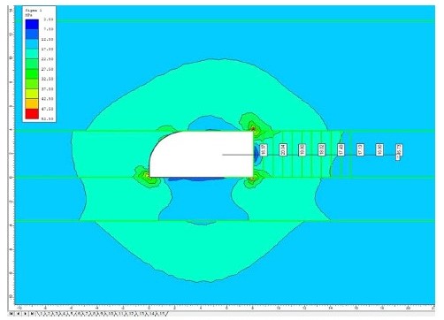
Fig. 6. Distribution of principal stresses during mining operations at +1.5 m from the roadway junction

Fig. 7. Distribution of principal stresses during mining operations at +9 m from the roadway junction
Fig. 4 illustrates the distribution of the maximum principal stresses σ1 in the near-excavation rock mass surrounding the roadway from which the new roadway is driven. The obtained stress distribution reflects the results of numerical modeling and makes it possible to identify zones of stress concentration and redistribution that arise due to the disturbance of the rock mass continuity during roadway development.
Analysis of the stress distribution shows that a pronounced zone of increased compressive stresses forms in the near-excavation region of the roadway roof and sidewalls. These stresses significantly exceed the background stresses of the undisturbed rock mass. The maximum values of σ1 are concentrated near the junctions of the excavation boundary with the sidewalls, which is caused by the geometric effect of excavation and the redistribution of loads within the rock mass. In the roadway floor, by contrast, a zone of reduced stresses is observed, associated with unloading of the rock mass and the development of tensile and shear deformations.
Fig. 5 presents the distribution of the maximum principal stresses σ1 in the rock mass during the driving of a new roadway from an existing roadway. The results obtained by numerical modeling characterize the changes in the stress–strain state of the rock mass in the roadway junction zone.
Fig. 6 illustrates the distribution of the maximum principal stresses σ1 in the near-excavation rock mass at the stage of mining operations at a distance of +1.5 m from the roadway junction zone. This stage of modeling reflects the evolution of the stress–strain state of the rock mass after the initial formation of the roadway junction and makes it possible to assess the spatial evolution of stresses as the excavation face advances away from the junction.
Fig. 7 shows the distribution of the maximum principal stresses σ1 in the rock mass at the stage of mining operations at a distance of +9 m from the roadway junction zone, which corresponds to the stage at which the roadway reaches a quasi-stationary stress state.
The obtained results indicate that at this distance the influence of the roadway junction zone on the overall stress field significantly decreases. The stress state of the rock mass becomes more symmetrical relative to the roadway axis, while the local stress concentrations previously recorded in the near-excavation zone of the junction transform into extended zones of moderate compressive stresses.
A stable zone of reduced σ1 values forms in the roadway roof, which corresponds to a developed unloading zone, whereas zones of elevated stresses remain in the side parts of the rock mass, defining the boundaries of the active influence of mining operations. In the roadway floor, the stress state becomes more uniform, indicating a reduction in the intensity of deformation processes compared with the initial stages of mining.
A comparison of the stress distributions at distances of +1.5 m and +9 m from the roadway junction shows that the main geomechanical effects associated with stress concentration are localized within a limited zone beyond the junction of the roadways. Outside this zone, the stress state of the rock mass stabilizes and is determined mainly by the mining depth and the physical and mechanical properties of the rocks.
As follows from the interpretation of the principal stress distribution, an abutment pressure zone forms in front of the excavation face during mining operations. Within this zone, stresses increase and reach 20.48 MPa, which is approximately 25% higher than the in-situ stress level characteristic of the undisturbed rock mass. This increase is associated with stress redistribution around the excavation caused by the local disturbance of rock mass continuity. From the standpoint of rock mechanics, such an increase in stress may affect roadway stability, especially in the presence of weak structural elements in the rock mass.
In addition, the interpretation presented in Figs. 5–7 reveals a zone of reduced stresses at the excavation face, indicating the presence of an unloading zone with a depth of up to 0.7 m. This phenomenon suggests possible loosening of the rock mass as well as partial destruction of the rock structure. Such unloading zones are typical of areas where local stress redistribution occurs as a direct result of mining operations.
The presence of such a zone must be taken into account because the loosened rock mass has reduced load-bearing capacity. This may lead to an increase in the volume of rock fall and complicate mining operations. To minimize these risks, special measures should be applied, such as reinforcement of the support system, grouting, or additional monitoring of the rock mass condition using geophysical methods.
To assess the extent of inelastic deformation zones and to identify areas susceptible to plastic deformation or complete failure, the most informative parameter for interpretation is the Factor of Safety (FoS). FoS allows a quantitative assessment of how close the current stress state of the rock mass is to its failure limit.
In software such as RS (e.g., Rocscience RS2 or RS3), the calculation of the FoS value is based on complex algorithms that account for the strength parameters of the rock mass. These calculations include physical and mechanical properties of rocks such as compressive strength, elastic modulus, cohesion, and internal friction angle, which determine the resistance of the rock mass to deformation and failure.
The main criterion for the development of inelastic deformation zones is the exceedance of the calculated stresses over the strength limits of the rock mass, which may lead to local failures, plastic deformation, and structural changes in the rock mass.
The application of FoS in data interpretation makes it possible not only to predict the behavior of the rock mass under loading but also to develop effective stabilization measures, such as selecting an optimal support system, modifying excavation parameters, or implementing compensatory engineering measures. Thus, the analysis of inelastic deformation zones using FoS becomes a key element in assessing the stability of underground mine workings. The distribution of the defined inelastic deformation zones is shown in Fig. 8.

Fig. 8. Distribution of inelastic deformation zones at the roadway junction
The use of the Factor of Safety (FoS) in interpreting the results of numerical modeling makes it possible not only to quantitatively assess the stability of the near-excavation rock mass but also to identify potentially hazardous zones where inelastic deformation may develop. Unlike the analysis of individual stress components, the FoS distribution provides an integrated characterization of the stress–strain state of the rocks while accounting for their strength properties.
As shown in Fig. 8, local zones with reduced FoS values (FoS < 1) are formed in the roadway junction zone, confined to the near-excavation regions of the roadway roof, floor, and sidewalls. These areas correspond to zones where the rock mass transitions into an inelastic state and represent potential sites for the development of failure, delamination, and intensive deformation.
Moving away from the excavation boundary deeper into the rock mass, a gradual increase in FoS values is observed, indicating a reduction in the influence of mining operations and the transition of the rock mass to a stable state. The spatial location of the boundaries of the inelastic deformation zones makes it possible to determine their depth of propagation and to use these data to substantiate the required length and arrangement of the support elements.
Analysis of the FoS distribution is a key element in the geomechanical justification of support parameters for underground mine workings. It enables rational selection of support types and parameters, prediction of the effectiveness of stabilization measures, and evaluation of the need for additional compensating solutions in the roadway junction zone.
The application of the proposed geomechanically justified approach to analyzing the stress–strain state of the near-excavation rock mass and selecting support parameters not only improves the stability of underground workings but also produces a cumulative economic effect by reducing operational and maintenance costs.
The main sources of economic benefit include:
Additional economic benefits are achieved through the possibility of predictive control of geomechanical processes. The use of numerical modeling and FoS analysis allows potentially unstable zones to be identified in advance and preventive engineering measures to be implemented, which is significantly less costly than eliminating the consequences of developed deformation.
The economic effect is achieved through the simultaneous reduction of capital and operating costs while increasing the reliability and service life of underground mine workings. The obtained results can serve as a basis for subsequent technical and economic calculations in the design and operation of underground excavations under similar mining and geological conditions.
For the considered computational model of the rock mass, it has been established that the inelastic deformation zone is localized in the near-excavation region of the excavation face and extends approximately 0.6–0.7 m into the rock mass. This zone is characterized by the maximum concentration of stresses and the development of intense plastic deformation caused by the redistribution of rock pressure during roadway driving. Within this region, the rocks lose their load-bearing capacity, accompanied by the destruction of their structural integrity and the formation of fragmented material, indicating the transition of the rock mass to a limit state.
Beyond the zone of developed inelastic deformation, within a depth interval of 0.7–1.8 (up to 1.9) m, a region of elastoplastic behavior of the rock mass is formed. In this interval, intensive fracturing processes occur, during which the rocks exist in a transitional state between elastic and plastic deformation. Although the overall stability of the rock mass is preserved, the development of fractures leads to a gradual decrease in its deformation stiffness and load-bearing capacity, which must be taken into account when determining the parameters of the support system.
At depths exceeding 1.8–1.9 m, the rock mass is characterized predominantly by an elastic state and at the considered moment is only weakly affected by mining operations. In this zone, the rocks retain high strength and their ability to sustain the acting stresses without developing significant deformation. At the same time, the possible evolution of the stress–strain state should be considered over the long term under the influence of time-dependent factors such as stress relaxation, rock creep, temperature effects, and further development of mining operations.
The obtained model of deformation distribution reflects the zonal character of rock mass stability disturbance, which requires a differentiated approach to stabilization. The zone of developed inelastic deformation requires the application of active and combined support methods that ensure stress redistribution and limit rock failure. In contrast, within the elastoplastic behavior zone it is advisable to use rock bolts designed to stitch fractured rock and enhance the overall integrity of the rock mass.
To ensure the safety and stability of underground workings, it is recommended to organize systematic geomechanical monitoring of the rock mass condition using instrumental and geophysical methods, as well as to adjust support parameters as mining and geological conditions evolve.
Within the framework of further development of the proposed mathematical model, several interrelated directions may be identified to increase its predictive reliability and expand its practical application under conditions of intensely deforming coal-bearing rock masses. These directions are based on integrating modern concepts of rock mechanics, the capabilities of numerical modeling, and the needs of mining production for substantiating support parameters.
Consideration of nonlinear deformation and failure kinetics. The current model operates with separate zones of elastic and inelastic behavior, whose boundary is determined empirically through the area Sd. For a more accurate description of the transition of the rock mass to the limit state, it is necessary to explicitly introduce a strength criterion into the system of equations. This would make it possible to calculate the configuration of the inelastic deformation zone not as a predefined parameter but as a function of the acting stresses and the rheological properties of specific rocks.
Particular importance should be given to the time factor and loading rate, since the strength and deformation characteristics of coal and host rocks of the Karaganda basin demonstrate pronounced rheological dependence. Modification of the strain-rate component u in equations (2) through the introduction of creep parameters or modeling of viscoplastic flow would allow prediction of displacement development not only during roadway driving but also during long-term roadway operation.
Structural-geological parameterization of the loosening coefficient. The loosening coefficient Kl in equation (3) is a key parameter but currently remains a generalized quantity. Its physical meaning can be significantly refined by relating it to quantitative characteristics of rock mass disturbance, including volumetric fracture density; orientation of fracture systems relative to the excavation boundary; roughness of fracture surfaces; granulometric composition of fragmented rock.
Such parameterization would allow differentiation of the loosening degree for the roof, floor, and sidewalls of the roadway, where different failure mechanisms dominate (spalling, shear, or floor heave). A further step could involve developing nomograms or analytical relationships linking Kl with the Rock Quality Designation (RQD) index, geophysical imaging data, or results of discrete element modeling (DEM), thereby enabling the transition from generalized estimates to specific mining-geological conditions of the site.
Development of a calibrated database and digital twin models for roadway development. The maximum practical benefit of the model can be achieved through its integration into an engineering decision-support system. For this purpose, it is necessary to create a library of calibration relationships based on both existing and future finite-element modeling sessions, as well as data from instrumental monitoring at real mining sites. These relationships should establish quantitative links between model parameters Sd and Kl and a set of controllable mining factors, including mining depth; span width; type and installation spacing of rock bolts; time delay between excavation and support installation. In the future, such a database may serve as the basis for creating digital twins of standard roadway development schemes. This will allow rapid scenario calculations of displacement and Factor of Safety values for different support configurations during the design stage, thereby optimizing engineering decisions in terms of stability, material consumption, and economic efficiency.
Development of the model along these directions will not only deepen the theoretical understanding of the processes governing the formation of inelastic deformation zones, but will also directly contribute to solving applied engineering problems. The result will be a more justified selection and adaptive management of support parameters, minimization of repair work volumes, and consequently an increase in the industrial safety and economic efficiency of underground coal mining.
Based on numerical modeling of the stress–strain state of a coal-bearing rock mass using the RS2 software package, considering the example of roadway development at a depth of 600 m, quantitative parameters and patterns of the formation of inelastic deformation zones were established, as well as their influence on the stability of underground workings and the selection of support parameters.
The performed geomechanical analysis confirmed that as the rate of rock deformation increases, the apparent strength limit of the rocks and the accumulation of elastic energy also increase, which, provided that permissible stress levels are maintained, reduces the probability of the formation of extensive failure zones in the near-excavation rock mass. However, a critical threshold was identified: when the calculated stresses exceed the strength characteristics of the rocks (for the studied conditions, stresses in the abutment pressure zone reach 20.48 MPa, which is about 25% higher than the background level), accelerated deformation leads to intensified loosening of the rock mass and the development of intense inelastic deformation within a zone 0.6–0.7 m from the excavation boundary.
A clear zonal pattern of rock mass deformation around the excavation was identified: a zone of developed inelastic deformation (0–0.7 m), a region of elastoplastic behavior with active fracturing (0.7–1.9 m), and a zone of predominantly elastic rock mass behavior (beyond 1.9 m). To reduce dilatancy caused by the relative displacement of fracture surfaces within the failure zone, it is recommended to control the deformation rate by installing support immediately after rock exposure, which is confirmed by modeling performed with an excavation advance step of 0.75 m.
Mining-geological conditions were found to have a determining influence: with increasing mining depth (600 m in the considered case), the initial stress state increases proportionally (σᵧ ≈ 16.4 MPa) and, accordingly, the potential for the development of inelastic deformation increases. At the same time, as the distance from the excavation boundary increases (beyond 1.9 m), the influence of mining operations decreases, the probability of dilatancy is significantly reduced, and the rock mass transitions to an elastic state, which is confirmed by the symmetry of the stress field at a distance of +9 m from the roadway junction.
To further reduce the degree of rock mass loosening and increase roadway stability, the need for a rational selection of the roadway cross-sectional shape is substantiated, which minimizes stress concentration and ensures a more uniform redistribution of stresses in the near-excavation rock mass. A reduction in local stress maxima, in turn, leads to a decrease in the size of failure zones.
It was established that directed modification of the structural characteristics of the rock mass is an effective tool for controlling its strength properties. Weakening leads to an expansion of failure zones, whereas active strengthening of the near-excavation rock mass by injection grouting or chemical stabilization increases the strength limit and deformation stiffness. When the achieved strength of the treated rock mass exceeds the acting stress level, the development of destructive processes and dilatancy is prevented, ensuring a stable state of the roadway and improving the safety of mining operations.
The implementation of a geomechanically justified approach based on analysis of the Factor of Safety (FoS) and the results of numerical modeling not only increases roadway stability but also generates a cumulative economic effect. Its sources include a reduction in the volume of repair and restoration work, decreased equipment downtime, reduced losses of the useful cross-section of roadways, optimization of support parameters and consumption of support materials, and an increase in industrial safety through early identification of zones with FoS < 1.
1. Djaksimuratov K. M., O’telbayev A. A., O’razmatov J. I., Mnajatdinov D. M. Properties of coal, processes in coal mining companies, methods of coal mining in the world. Journal NX. 2021;7(10):231–236. URL: https://repo.journalnx.com/index.php/nx/article/view/3681/3548
2. Batyrkhanova A., Tomilov A., Zhumabekova A., Abekov U., Demin V. Developing technological schemes of driving workings with controlled resistance of contours. Naukovyi Visnyk Natsionalnoho Hirnychoho Universytetu. 2019;(3):22–28. https://doi.org/10.29202/nvngu/2019-3/2
3. Akhmatnurov D., Zamaliyev N., Mussin R., Demin V., Tolovkhan B., Ganyukov N., Skrzypkowski K., Korzeniowski W., Stasica J., Rak Z. Geomechanical modeling of the Northern Katpar Deposit (Kazakhstan): Assessing the Impact of Rock Mass Disturbance on Stability Safety Factor. Mining. 2025;5(4):73. https://doi.org/10.3390/mining5040073
4. Budi G., Rao K. N., Mohanty P. Field and numerical modelling on the stability of underground strata in longwall workings. Energy Geoscience. 2023;4(1):1–12. https://doi.org/10.1016/j.engeos.2022.07.003
5. Xiong Y., Kong D., Wen Z. et al. Analysis of coal face stability of lower coal seam under repeated mining in close coal seams group. Scientific Reports. 2022;12(1):1–14. https://doi.org/10.1038/s41598-021-04410-5
6. Nehrii S., Nehrii T., Zolotarova O., Volkov S. Investigation of the geomechanical state of soft adjoining rocks under protective constructions. Rudarsko-Geološko-Naftni Zbornik. 2021;36(4):61–71. https://doi.org/10.17794/rgn.2021.4.6
7. Lama B., Momayez M. Review of non-destructive methods for rock bolts condition evaluation. Mining. 2023;3(1):106–120. https://doi.org/10.3390/mining3010007
8. Цай Б. Н., Судариков А. Е. Механика подземных сооружений. Караганда: КарГТУ; 2007. 159 c.
9. Tsay B. N., Sudarikov A. E. Mechanics of underground structures. Karaganda: KarGTU; 2007. 159 p. (In Russ.)
10. Taran I. Interrelation of circular transfer ratio of double-split transmissions with regulation characteristic in case of planetary gear out-put. Naukovyi Visnyk Natsionalnoho Hirnychoho Universytetu. 2012;(3):78–85.
11. Huang W., Liu S., Gao M. et al. Improvement of reinforcement performance and engineering application of small coal pillars arranged in double roadways. Sustainability. 2022;15(1):292. https://doi.org/10.3390/su15010292
12. Demin V. F., Demina T. V., Kaynazarov A. S., Kaynazarova A. S. Evaluation of the workings technological schemes effectiveness to increase the stability of their contours. Sustainable Development of Mountain Territories. 2018;10(4):606–617. (In Russ.) https://doi.org/10.21177/1998-4502-2018-10-4-606-616
13. Shashenko A., Gapieiev S., Solodyankin A. Numerical simulation of the elastic-plastic state of rock mass around horizontal workings. Archives of Mining Sciences. 2009;54(2):341–348.
14. Nemova N. A., Stakhanov D., Hasan B., Zhumabekova A. E. Technological solutions development for mining adjacent rock mass and pit reserves taking into account geomechanical assessment of the deposit. Naukovyi Visnyk Natsionalnoho Hirnychoho Universytetu. 2020;(2):17–24. https://doi.org/10.33271/nvngu/2020-2/017
15. Smoliński A., Malashkevych D., Petlovanyi, M. et al. Research into impact of leaving waste rocks in the mined-out space on the geomechanical state of the rock mass surrounding the longwall face. Energies. 2022;15(24):9522. https://doi.org/10.3390/en15249522
16. Sotskov V., Saleev I. Investigation of the rock massif stress strain state in conditions of the drainage drift over-working. In: Pivnyak G., Bondarenko V., Kovalevs'ka I., Illiashov M. (Eds.) Mining of Mineral Deposits. CRC Press; 2013. Pp. 197–201. https://doi.org/10.1201/b16354-35
17. Yang H., Han C., Zhang N. et al. Research and application of low density roof support technology of rapid excavation for coal roadway. Geotechnical and Geological Engineering. 2020;38:389–401. https://doi.org/10.1007/s10706-019-01029-2
18. Bondarenko V., Symanovych G., Koval O. The mechanism of over-coal thin-layered massif deformation of weak rocks in a longwall. In: Bondarenko V., Kovalevs'ka I., Illiashov M., Pivnyak G. (Eds.) Geomechanical Processes During Underground Mining. CRC Press; 2012. Pp. 41–44. https://doi.org/10.1201/b13157-8
Vladimir F. Demin – Dr. Sci. (Eng.), Professor of the Department of Mineral Deposits Development
Karaganda
Scopus ID 57212219714
Niyaz G. Valiev – Dr. Sci. (Eng.), Deputy Chairman of the Academic Council, Head of the Mining Department; General Director, Mining Industry Association of the Urals
Yekaterinburg
Scopus ID 55749527900
SPIN 3886-5864
Denis R. Akhmatnurov – PhD, Head of the Methane Energy Laboratory
Karaganda
Scopus ID 57194187849
SPIN 1396-9321
Ravil A. Mussin – PhD, Associate Professor of the Department of Mineral Deposits Development
Karaganda
Scopus ID 7005446397
Ravil A. Mussin – PhD, Associate Professor of the Department of Mineral Deposits Development
Karaganda
Scopus ID 7005446397
Demin V.F., Valiev N.G., Akhmatnurov D.R., Mussin R.A., Zamaliyev N.M. Formation of inelastic deformation zones based on numerical modeling. Mining Science and Technology (Russia). 2026;11(1):90-102. https://doi.org/10.17073/2500-0632-2025-07-1104




Editor-in-Chief
Petrov V.L. Email this article (Login required)
Email the author (Login required)
Email this article (Login required)
Email the author (Login required) 119049, Moscow, Leninsky Prospect, 4, b. 1
The National University of Science and Technology MISIS (NUST MISIS)
Tel.: +7 (968) 848-61-24
E-mail: send@misis.ru