Scroll to:
New advances in drilling operations in sandstone, shale, and carbonate formations: a case study of five giant fields in the Mesopotamia Basin, Iraq
https://doi.org/10.17073/2500-0632-2023-08-146
Abstract
Drilling challenges in the Mesopotamian Basin, Southern Iraq, are varied and include such issues as mud loss, bit damage, and differential sticking. This study aims to analyze these problems across the stratigraphic column in the study area. The results show that the MMD65R, EQH16R, and SF74R bits were successfully used for the 16” section, while the MSi616L bit was the most efficient for the 12¼” section. The MMD65R was suitable for the 8½” section, with the EQH12DR bit being used for the remaining parts of this section. The MMD54 bit showed excellent performance, achieving the highest rate of penetration (ROP) of 26.9 m/hr in well horizontal sections. Mud losses were most commonly observed at the base of the Dammam, Rus, Tanuma, Mishrif, Hartha, Shuaiba, and Zubair Formations. An appropriate drilling mud density is 1.28 sg is recommended for Zubair and Mishrif Formations. Additionally, tripping in/out operations must be conducted at controlled speed to prevent surging or swabbing the well. Potassium Chloride concentrations should be maintained between 3 to 5%. A 7” production liner must be run and properly seated to isolate the Mishrif and Zubair Formations, with overlap to prevent potential communication between lower water-bearing zones and shallow loss zones.
Keywords
For citations:
Al-Dujaili A.N. New advances in drilling operations in sandstone, shale, and carbonate formations: a case study of five giant fields in the Mesopotamia Basin, Iraq. Mining Science and Technology (Russia). 2024;9(4):308-327. https://doi.org/10.17073/2500-0632-2023-08-146
New advances in drilling operations in sandstone, shale, and carbonate formations: a case study of five giant fields in the Mesopotamia Basin, Iraq
Acronyms and Abbreviations
| API | American Petroleum Institute |
| BHA | Bottom Hole Assembly |
| DD | Directional Driller |
| ECD | Equivalent Circulating Density |
| GPM | Gallons per Minute |
| LCM | Lost Circulation Materials |
| MD | Measured Depth |
| MJ | Majnoon Field |
| MW | Mud Weight |
| NPT | Non-Productive Time |
| PDC | Polycrystalline Diamond Compacts |
| POOH | Pull Out of The Hole |
| PV | Mud Viscosity |
| RKB | Rotary Kelly Bushing |
| ROP | Rate of Penetration |
| RPM | Revolutions per Minute |
| RSS | Rotary Steerable System |
| Ru | Rumaila Field |
| SPM | Strokes per Minute |
| SSP | Site Safety Plan |
| TFA | Total Flow Area |
| WOB | Weight on Bit |
| WQ | West Qurna Field |
| YP | Yield Point |
| Zb | Zubair Field |
Nomenclature
| HR | Hour |
| Deg. | Degree |
| RR | Re-Runnable |
| In | Inch |
| Ft | Foot |
| H2S | Hydrogen Sulfide |
| L | Liter |
| M | Meter/s |
| Min. | Minute |
| BBL | Barrel |
| Avg. | Average |
| ID | Inside Diameter (in) |
| PP | Pore Pressure (Psi) |
| FG | Fracture Gradient |
| KCl | Potassium Chloride |
Introduction
Wells drilling and completion account for over 40% of all investments in the hydrocarbon energy industry. Reducing failures during the drilling process is one of the key prospects for increasing effective drilling time and addressing challenges faced during drilling and their consequences. The main types of complications in the wells drilling process include sticking of the drill string due to deviation, collapsing of unstable rocks, narrowing of the wellbore from crumbling rocks, absorption of drilling mud, gas-oil-water showings, and brine showings [1]. All drill cuttings must be removed from the well during drilling and brought to the surface, a process referred to as hole cleaning [2]. However, some material often remains in the well, leading to issues such as pipe sticking, premature bit wear, slow drilling, formation damage (fracturing), excessive torque and drag, and difficulties in logging and cementing [3].
Complete or partial loss of drilling mud within a formation during the drilling operation, or a situation where the amount of mud recovered from the well does not match the amount injected, is known as drilling fluid loss or retrieval loss [4]. This typically occurs in highly permeable, depleted reservoirs, natural cracks, cavernous formations, and fracture formations [5]. Various techniques are employed to control circulation loss, such as reducing the density of the drilling mud [6], and adding lost circulation materials (LCM) to plug and seal loss zones [7]. Multiple factors may affect drilling fluid loss, including petrophysical properties (porosity, permeability, etc.), characteristics of the drilling mud itself (MW, ECD, YP, PV, etc.), drilling parameters (ROP, WOB, RPM, SPM, SSP, TFA, etc.), and pressure conditions (pore pressure gradient, fracture pressure, etc.) [8]. 54% of stuck pipe incidents examined occurred while tripping and back reaming [9]. The risk of stuck pipe incidents has increased due to the recent expansion of drilling activities, particularly in depleted and higher-risk reservoirs [10]. Several studies suggest using statistical methods to predict stuck pipe events [11].
Salih et al. (2018) studied the formations of southern Iraqi oilfields, providing a detailed description from the Upper Fars to the Mishrif formations. The severity of problem in each formation were defined by identifying the causes of issues in the wells or potential risks [12]. Losses are predictable in the Rumaila oilfield at the base of the Dammam Formation, where water ingress occurs during the drilling process. Losses have also been reported in the Hartha Formation, and significant washout have been observed in the Tanuma Formation. The variability of the Mishrif reservoir’s architecture and rock types may cause irregular sweep and water breakthrough if higher permeability layers are present. Sloughing formations include the Tanuma, Nahr Umr, and Upper Shale formations. Loses may also occur in the Mishrif and Zubair formations, with potential pipe sticking through the Mishrif, Nahr Umr, and Zubair formations. Bit damage during drilling through anhydrite layers (Lower Fars and Rus Formations) has a lesser effect on the drilling program [13].
1. Geological setting
Iraqi territory is represented by four major tectonic zones. These zones can be classified according to several factors such as rock type, age, thickness, and structural transitions. The zones are [14]:
- interior settled shelf;
- exterior unsettled shelf;
- Shalair territories;
- Zagros.
The interior and exterior regions of the Arabian Plate are characterized by the absence of metamorphosis and volcanic activities. The Mesopotamia Plain and the Jazira Plain are the main parts of the Mesopotamia Foredeep in Iraq. This foredeep is characterized by being less tectonically problematic and is formed from quaternary alluvial deposits of the Tigris and Euphrates Rivers and their tributaries, which completely cover the central and southeastern parts of the basin. Wrapped with Miocene rocks, the Jazira Plain marks the extension of the Mesopotamia Plain towards the northwest [15]. The Mesopotamia basin generally has a flat topography. Surface structures resulting from tectonic activity are scarce in this basin, but it contains several structures, including faults, folds, and diapiric structures [16].
The stratigraphic column of southern Iraq [17, 18] is characterized by a thick Cretaceous depositional sequence with significant hydrocarbon accumulations in many formations [19] (Fig. 1, a).
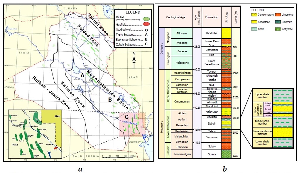
Fig. 1. Locations of the wells under study and their drilling dates – a; Stratigraphic column in southern Iraq – b [17, 18]
1.1. Majnoon Field
Majnoon Field comprises a banana-shaped, crested anticline with a general N-S elongation [20]. It represents a compression fold, likely underlain by salt below the Jurassic level. The field consists of four major and seven minor reservoirs from the Lower Cretaceous to Paleocene age, spanning a vertical interval of about 3000 m [21]. The four main reservoirs, in-depth order, are the Hartha, Mishrif-Ahmadi, Nahr-Umr, and Zubair formations, with the deepest being the high-pressure Yamama carbonate formation. These account for 80% of Majnoon’s hydrocarbons. The Yamama and Mishrif formations alone account for 50% of the major reservoir volume. The minor reservoirs may indicate hydrocarbons in the Khasib, Sadi, Tanuma, Ghar, Shiranish, and Shuaiba Formations [22] (see Fig. 1, a).
1.2. Rumaila Field
The Rumaila field is a supergiant oilfield located 50 km west of Basrah city in southern Iraq [23]. It has stacked pay in multiple clastic and carbonate reservoirs. The Rumaila field was discovered in 1953 and accounts for 33% of Iraq’s total oil production. The Rumaila structure represents a mildly tilted longitudinal anticline, extending approximately 83 km in length and 12 km in width [24]. Two faults, Takadid-Qurna and Al-Batin, extend from the northeast to the southwest. These faults are reactivated Precambrian transverse faults that define the Zubair fault block or subzone of the Mesopotamian basin [25] (see Fig. 1, a).
The most significant hydrocarbon system in this stratigraphic column is the Early Cretaceous–Miocene petroleum system. In this system, the Sulaiy and Yamama formations serve as source rocks; the Tanuma, Shranish, and Rus formations act as sealing rocks; and the Yamama, Zubair, Nahr Umr, and Mishrif formations serve as reservoir rocks [26] (Fig. 1, b).
1.3. West Qurna (1 and 2) Field
Iraq’s supergiant oilfields are mainly located in southern Iraq, and one of these is the West Qurna oilfield [27, 28]. It is located northwest of Basra city, within the Zubair Subzone, and is structurally part of a large isocline to the North. The field is estimated to contain approximately 30 to 40 billion barrels of recoverable reserves [29]. The West Qurna oilfield represents the northern extension of the supergiant Rumaila oilfield [30] (see Fig. 1, a).
1.4. Zubair Field
The Zubair Field is located within the Mesopotamian zone, on the unstable sill of the Arabian Platform [31]. Zubair is one of the mature oilfields in southern Iraq, located 20 km southwest of Basra city [32] (see Fig. 1, a).
This field was discovered in 1949, consisting of four domes (Al-Hamar, Shuaiba, Rafidyah) in the NW and (Safwan) to the SE, connected through an aquifer that extends beyond the Iraqi and Kuwaiti border [33]. The field structure includes four reservoirs: Mishrif, Upper Shale Membrane, and the Third and Fourth Pay zone [34].
1.5. Productive Formations
The Mishrif Formation is divisible by a prominent unconformity into two large-scale regressive sequences, particularly distinguishable in the east of the Mesopotamian Basin. Multiple reservoir units are present in both sequences. The west of the basin is dominated by the lower sequence, which has relatively few reservoir intervals. The shallow-water reservoir units in the east are thick, reflecting relatively high subsidence rates during the Cenomanian [35]. Subsidence rates in the western side of the basin were lower, resulting in thinner and more limited reservoir units.
The best reservoir conditions in the Mishrif Formation occur in rudist-bearing facies, such as rudstones and rudistid packstone/grainstones [27] (Fig. 2, a).
The Mauddud Formation is a shallow-water carbonate, distributed widely in the subsurface of the Persian Gulf. It is recognizable in the Northern Gulf (Iraq and Kuwait), eastern Arabia (Saudi Arabia, Bahrain), and the Southern Gulf (United Arab Emirates and Oman) [36]. In southern Iraq, the formation was described from the Zubair-3 well by Owen and Nasr (1958) (Fig. 2, b). The Mauddud Formation consists of organic, detrital, and occasionally pseudo-oolitic limestone with streaks of green or bluish shale [37].
The Zubair Formation, dating from the early Cretaceous (Hauterivian to Early Aptian), is aregionally extensive oil-producing sandstone sequence found in Syria, Iraq, and Iran [38]. The Zubair sandstones are environmentally and genetically similar to the Nahr Umr sandstones of the Kuwaiti fields, consisting of clean, well-sorted quartz arenites, sourced from the Arabian shield and deposited from west to east into the Mesopotamian Basin during the Early Cretaceous. The Zubair sandy deposits comprise numerous depositional cycles composed of shallowing-upward successions of dark grey shale, siltstone, and fine- to medium-grained sandstone [39] (Fig. 2, c). These cycles are interpreted as a series of sea-level transgressions and regressions during a longer-term transgression. Typical lithofacies within these cycles include marine shelf, prodelta, delta front, and delta plain [40]. Litho-stratigraphically, the formation is subdivided into five sub-units:
- Upper Shale Member: contains isolated, massive (10–15 m-thick) oil-bearing sandstones. This unit has been producible from a few wells (e.g. Zb-X7).
- Upper Sandstone Member (Third Pay): contains stacked pay sands and 32° API gravity oil. This reservoir unit has been producible from about 80 wells.
- Middle Shale Member.
- Lower Sandstone Member (Fourth Pay): contains stacked pay sands with 38° API gravity oil. This unit has been producible from eight wells.
- Lower Shale Member.
Each reservoir unit is isolated by intervening shaly zones. The reservoir drive mechanism is mainly gas expansion, with a weak to moderate water drive [41].
The Yamama Formation is the primary Lower Cretaceous carbonate reservoir in southern Iraq, belonging to the late Berriasian-Aptian cycle. It is described from the shore to the deep basin by the Zubair, Ratawi, Yamama, Shuiaba, and Sulaiy formations [42]. The Ratawi Formation usually conformably overlies The Yamama Formation. In SE Iraq, at the Nasiriya, West Qurna, and Majnoon fields, probable sequence boundaries can be identified within the Yamama Formation of the top of oolite facies. In southern Iraq, the Yamama Formation is recognized by the presence of limestone below the last shale streak at the base of the Ratawi Formation [43]. The Yamama Formation is one of the most important oil-producing reservoirs in the southern Mesopotamian zone (West Qurna, North Rumaila, and Majnoon fields) and extends from the Valanginian to Early Hauterivian within the main retrogressive depositional cycle (Berriasian-Aptian) in the southern Iraq [42] (Fig. 2, d).
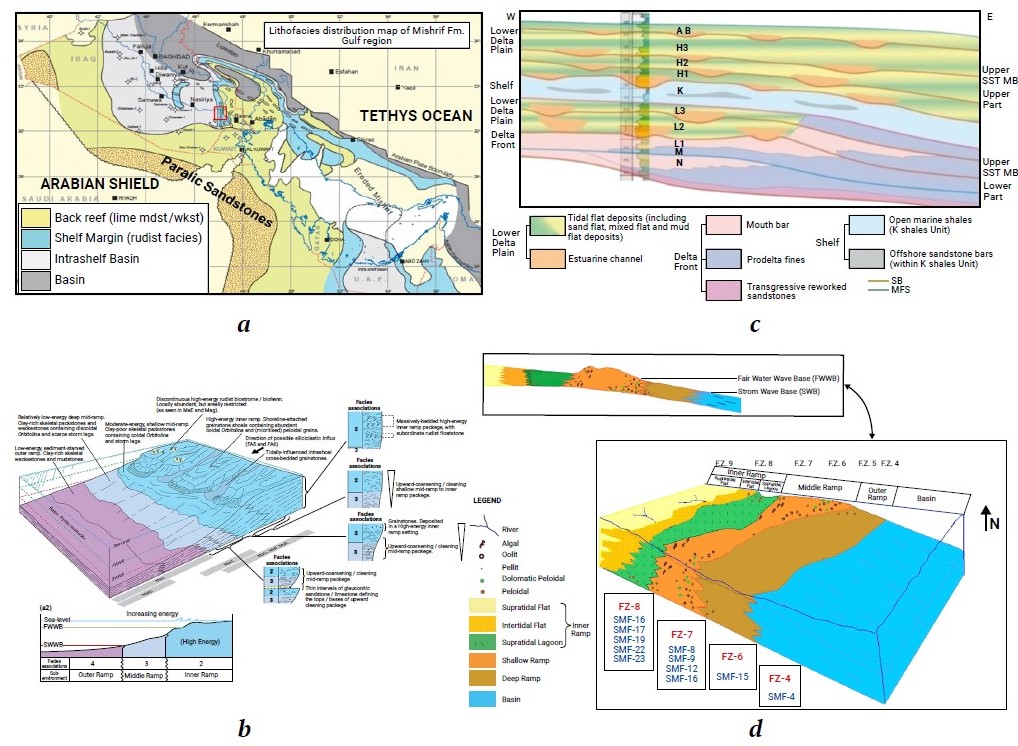
Fig. 2. Lithofacies distribution for the Mishrif Formation in the Gulf Region – a [44]; Depositional model for Mauddud – b [37]; Zubair – c [ZFOD, (Zubair Field Operating Division). Sedimentological and Reservoir Quality Study of the Zubair Formation. 2014. (Unpublished Study)]; Yamama – d [45] Formations
2. Historical Review of drilling operations
The problems encountered during drilling processes in southern Iraq formations can be summarized in (Fig. 3), based on a previous study that discussed these issues [13], which will be adapted in this research. Losses should be expected at the base of the Dammam Formation and in the Hatha, Mishrif, and Zubair Formations. A significant washout occurred in the Tanuma Formation. The variability of Mishrif reservoir architecture and rock types might lead to irregular sweep and water breakthroughs. Sloughing formations are represented by Tanuma, Nahr Umr, and Upper Shale. The potential of stuck pipes is noticeable in the Mishrif, Nahr Umr, and Zubair Formations. Bit damage during drilling through entire anhydrite layers in the Lower Fars and Rus Formations was a problem, though with a lower impact on the drilling program. The Dammam Formation faced the most drilling problems, according for 56.4% of all wells drilled (caving and mud loss), while no significant issues were reported in the Dibdibba, Khasib, Rumaila, Ahmedi, Mauddud, and Shuaiba Formations [46].
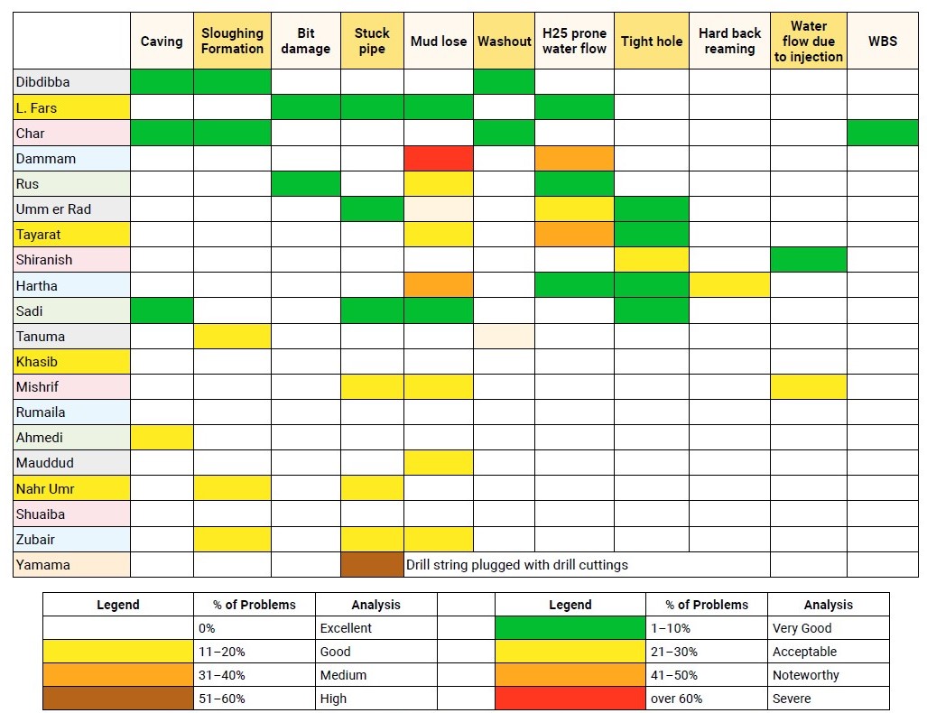
Fig. 3. Analysis of drilling problems for each formation in the Rumaila Field [13]
3. Methodology
The wells, which can be relied upon to achieve the results of this research, can be divided into seven groups according to the date of the drilling process. Fig. 4 shows the locations of the wells under study and the date of the drilling process.
Data were utilized from 10, 8, 12, and 6 wells in the Majnoon, Rumaila, West Qurna (1 and 2), and Zubair Fields, respectively. In addition, data were obtained from the offset wells in these fields (see Fig. 1, a).
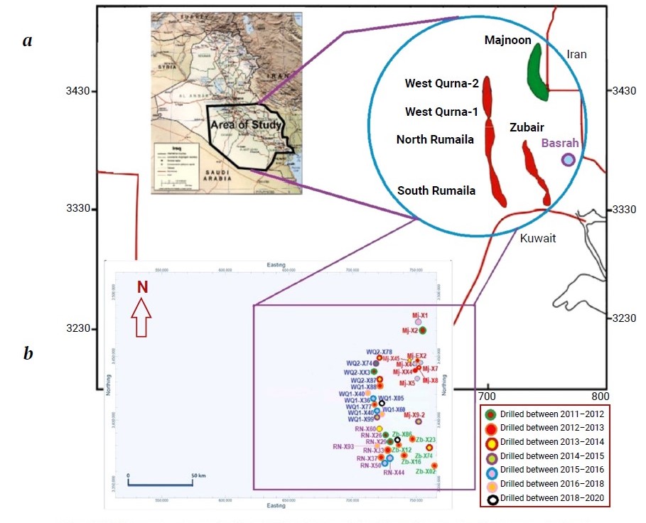
Fig. 4. Well groups categorized by drilling date and their locations in the Mesopotamian basin
3.1. Bit performance
The most suitable drilling technique varies with the conditions and equipment, so modifying the recommendations for drilling might be considered to obtain the best results. The effect of such changes on the drilling rate must be carefully examined, especially if these changes do not immediately increase the drilling rate.
3.1.1. For the Rumaila Field
From 2011 to 2013, 22 bits of the MSi616L type design were tested in 24 wells on different drive types in the Rumaila Field before being run in R-X33 to experiment with the best performance.
3.1.2. For the Majnoon Field
The 16” SFD75D bit type was used in 25 directional wells from 2012 to 2016, starting with well MJ-X2. The same bit was used again in wells MJ-X4 and MJ-X5, while the SFD76C bit type was tested in well MJ-X7.
3.1.3. For the Zubair Field
Four new bits types were tested in 18 wells on different drive types in the Zubair Field from 2012 to 2014, aiming to improve performance based on lessons learned in the previous fields (Table 1).
Table 1
Bit types used in the Zubair Field
Size | Type | New/Used | Nozzles |
26'' | VE598 | Used | – |
26'' | CKL | New | – |
16" | VGA-T318 | New | – |
81/2" | HC506ZX | New | without nozzles |
81/2" | RC216 | New | without nozzles |
121/4" | GT-1 | Used | without nozzles |
121/4" | Q506FX | Used | 6 x 13/32 |
3.1.4. For the West Qurna 1 and 2 Field
Several well trajectories with different targets were drilled in the WQ Field, including S-Shape, J-Shape, and horizontal wells, during the period from 2015 to 2018. The 12¼” SFE66DH bit type was used with an ROP of 15.81 m/hr through the Dammam, Rus, Umm Er Radhuma, Tayarat, Shiranish, Hartha, and Sadi formations.
The 15.8 is considered the second-best ROP achieved throughout the horizontal wells in this field. The directional plan for the 12¼” section was to hold the inclination angle at 12–15º, then built the inclination to 20º, and finally hold it at 20–22º.
The MME65R bit type was used to drill the 8½” section due to losses encountered in the Mishrif Formation. The same bit was used to drill out the cement plug through this formation.
3.2. Lost Circulation
Lost circulation is a common problem encountered during drilling and cementing operations. It can range from being a minor issue to a major, dangerous, and expensive problem due to loss of mud and rig time. A host of leading-edge technologies was implemented to solve lost circulation problems. Fig. 5 shows the well design for different types of wells and for different productive zones.
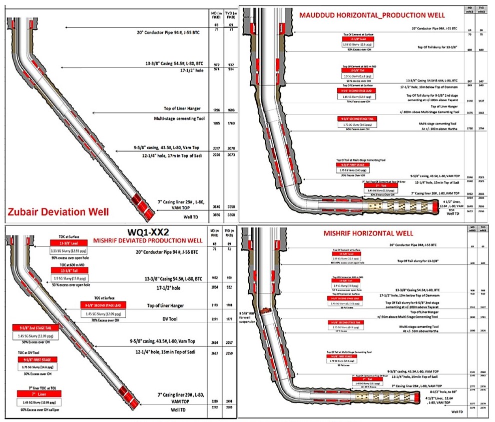
Fig. 5. Well schematic for the wells by Powerdraw TM [46]
3.2.1. For Non-Productive Formations
Potential losses in the Dammam, Rus, and Hartha formations can be considered the main challenges during the drilling process. Controlling the ROP or POOH was adopted to overcome losses in these formations. The drilling program for wells in these formations includes using a 12¼” slick BHA with large nozzles and pumping a balanced cement plug through the bit.
3.3. Other Problems
- Sulfurous water may be present in the Umm-Er-Radhuma and Tayarat Formations.
- The potential release of H2S while drilling the Nahr Umr sandy formation poses serious health risks for humans and the environment.
- Hole instability issues may be observable in the Nahr Umr Formation.
- The Mishrif is a depleted reservoir prone to mud losses and stuck pipes if not adequately bridged.
- Swelling shales lead to tight over-pulls and sloughing, with a risk of caving, which can result in stuck pipes in the Nahr Umr Formation.
- Shale instability and cavings are observed in shale membrane zones for the Zubair Formation.
- The variability of reservoir architecture and rock types in the Mishrif, Mauddud, Zubair, and Yamama reservoir might lead to irregular sweep and water breakthrough if higher permeability layers are present.
4. Results
4.1 Bit Performance
4.1.1 Rumaila Field
Twenty-two bits of the MSi616L type design were used in 24 wells on different drive types in the Rumaila Field before being run in well R-X33. A summary of the MSi616L type bit performance is as follows (Fig. 6).
The bit records for the 12¼” MSi616L type design in offset wells indicate a median drilling distance of 1000m per bit and a median ROP of 13 m/hr per run. (see Fig. 6).
According to Fig. 7, the majority of the cutting structure on this bit is green. There are a couple of broken cutters, one on the outer cone area of Blade #1 and the other on the nose of Blade #6.
Fig. 8 shows a comparison of drilling parameters between the MSi616L and QD506FX bit for the Shiranish Formation (1642–1835m) in well R-X33 in the Rumaila Field. The bit records for the 12¼” MSi616L design in offset wells indicate a median drilling distance of 1000m per bit and a median ROP of 13 m/hr per run. Thus, the 12¼” MSi616L is a well-proven design in the Rumaila application.

Fig. 6. Performance of MSi616L type bits in the Rumaila Field
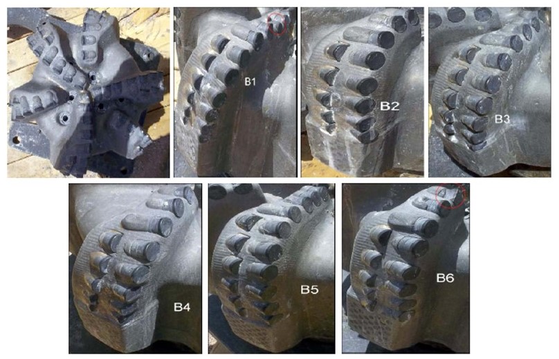
Fig. 7. 12¼” MSi616LPX (JF4376) bits from the wells studied in the Rumaila Field
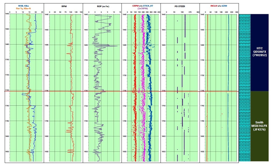
Fig. 8. Section drilled by 12¼" QD506FX & MSi616LPX bits in the Shiranish Formation (1642–1835 m) for well R-X33
4.1.2. Majnoon Field
The 16” SFD75D bit was run similarly after being used in well MJ-X2 to drill 1822 m cumulatively in wells MJ-X4 and MJ-X5. The ROP performance in these wells averaged 27m/hr, and the cutting bit had 7 blades with 19mm of cutters. Fig. 9 shows a comparison between different kinds of bits used in the Majnoon Field.
In well MJ-X3, which achieved the highest ROP and fewer trips, the 8½” MMD65R bit was successfully used on a motor assembly, achieving an ROP of 16.7 m/hr. The drive system was changed from POOH to the RSS, and the 8½” MME74H was used to complete the section, achieving an ROP of 16 m/hr (Fig. 10).
The performance comparison between different types of bits (Majnoon Field as an example) shows that MMD65R, EQH16R, and SF74R are the best bits for drilling the 16" section (Fig. 11).
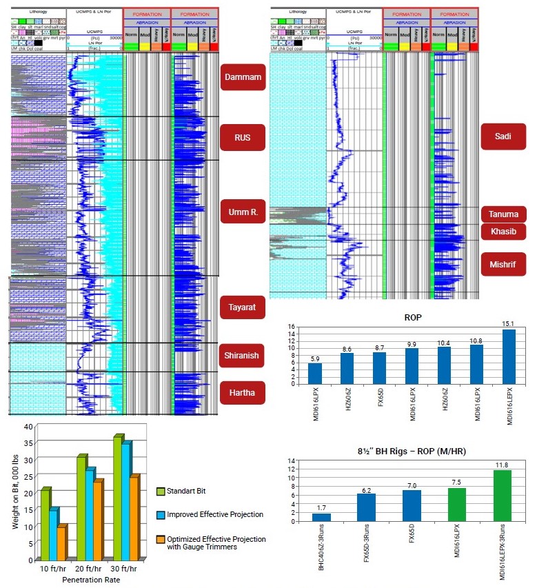
Fig. 9. Comparison of performance for all types of bits used in the Majnoon Field
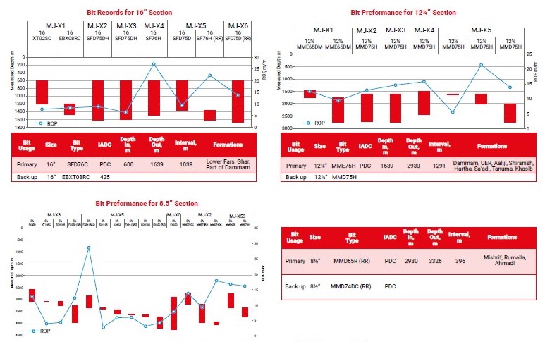
Fig. 10. Bit performance in the Majnoon Field
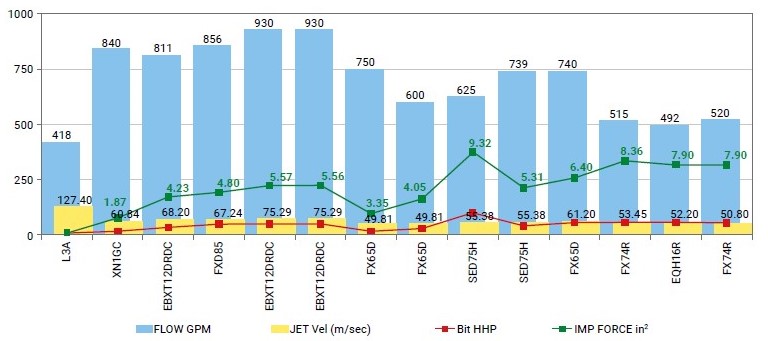
Fig. 11. Comparison of hydraulic performance for 16” bits used in the Majnoon Field
4.1.3. West Qurna-1 and 2 Field
The horizontal sections drilled show consistent performance in the field in terms of ROP and bit condition. The higher performance was achieved in well WQ1-X54, where 601m was drilled by the MMD64DR bit (6 blades, 13 mm cutter size) at an ROP of 27.3 m/hr. The MMD54 bit (5 Blades, 13 mm cutter size) also showed excellent performance, achieving the highest ROP of 26.9 m/hr in well WQ1-X55, with an excellent accumulated interval throughout the field. A total of 1340 m was drilled in wells WQ1-X57, WQ1-X59, and WQ1-X60 (2nd run) using the MMD54 bit (Fig. 12).
The Fig. also indicates that bit performance in the Yamama Formation for well WQ1-X38 was better than the well WQ1-X63 in terms of ROP and bit condition.
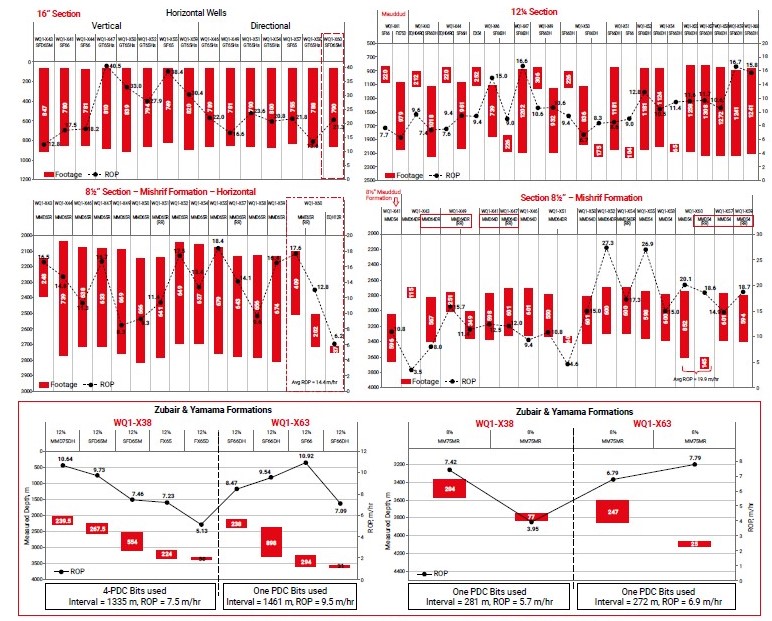
Fig. 12. Bits performance through the non-productive and productive zones (Mishrif, Mauddud, Zubair, and Yamama Formations) in the West Qurna Field
4.1.4. Zubair Field
No data are available for bit performance in this field.
Some of the wells drilled before 2011 (R-XX3 and XX8) experienced stick-slip levels throughout the two PDC runs. Despite variations in formations, formation strengths, drilling parameters, or bit cuttings structures, there was no considerable difference in stick-slip levels (~2xCRPM during both PDC runs). Collar RPM fluctuations were wide in the UER formation but narrowed in subsequent formations, with no change to stick-slip levels (Fig. 13). No significant stick-slip was observed in the wells under study, either Rumaila or other fields, due to the performance of the MSi616LPX bit, which showed no severe vibration levels at the bit with the given drilling parameters and rock types (Fig. 14).
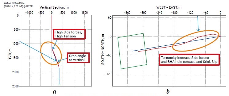
Fig. 13. Tortuosity – a; Side forces for well R-XX3 – b
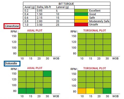
Fig. 14. Sensitivity of axial and torsional torques (RPM vs WOB) for limestone and dolomite formations in the Rumaila Field
4.2. Lost Circulation
Losses for cutting displacements/losses in the Dammam and Rus formations can be noticeable. The lost-circulation control materials used are FlexPlug, FlexPlug W, FlexPlug OBM, and FlexPlug R, which can be pumped through most BHAs and react with the drilling mud to create a barrier at the face of the zone in the wellbore rather than penetrating the matrix or fracture. Therefore, this technique is less damaging to potentially productive formations.
The mitigation program includes several possibilities: first; if losses are 1–2 m3/hr, ROP will be below 10 m3/hr, and an LCM quantity of 10 m3 (with a density of 45 lb/bbl) will be pumped. When the losses exceed 2 m3/hr, the drilling process will be stopped, and a ball will be dropped to open the PBL sub-circulating valve, ollowed by the pumping of 10–20 m3 of LCM (with a density of 85 lb/bbl). In addition, the annulus around the bit will be opened. In the case of total losses, the PBL sub-circulating valve will be opened, and if no returns are observed, an LCM quantity of 20 m3 (with a density of 85 lb/bbl) will be pumped (Fig. 15).
Downward from the Mishrif Formation, another non-productive formation, the Shuaiba Formation, also shows the mud loss phenomena. Fig. 16 indicates mud loss areas, where the red outline encloses the area of severe mud loss, while the black outline indicates partial mud loss. The green outlines arbitrarily mark areas where no mud loss was recorded. It should be noted that the embedded values reflect variable drilling practices and may change in a biased way, either increasing or decreasing.
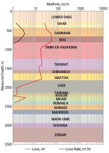
Fig. 15. Mud loss from the surface to the Rumaila Formation
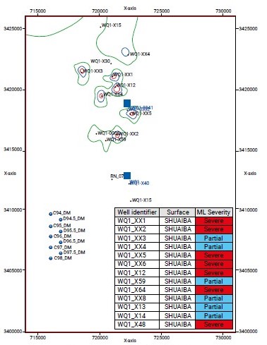
Fig. 16. Mud loss mapping for the Shuaiba Formation in the West Qurna (1 and 2)
4.3. Mitigations for Other Problems
The Mishrif, Mauddud, Zubair, and Yamama Formations must be isolated from the top of the liner to eliminate crossflows and pretend potential communication between the lower water-bearing zones and shallow loss zones during the production phase of the wells.
H2S detectors must be calibrated and functionally tested before drilling into the Nahr Umr Sandy Formation. The 8½’’ BHA wipe trip could not pass through the POOH in the Nahr Umr Formation, and re-running with directional BHA was required to clear the obstruction. Surging/swabbing issues were observed in the wells in the Zubair Formation, with the presence of connection gas, background gas, trip gas, and differential sticking.
The 8½” interval in the Zubair Formation will be drilled with an inhibitive KCL/PHPA polymer mud system to provide wellbore hole stability, clay inhibition, and good hole cleaning. Glycol will be used if required, with 3% added in the case of shale problems. CaCO3 will be added to increase mud weight to the desired 1.28 sg.
For the Yamama Formation, the PDC Bit (MMD65R) performed the best. Mud properties should have an MW of 1.60–1.65 sg (as indicated in the last two rows of Table 2). GEM™ GP shale stabilizer and KCl Polymer (5% KCL) must be added, with a flow rate of 1800–2300 LPM, and RPM adjusted as per the DD's recommendations.
Table 2
The Yamama offset wells data and MW selection in the West Qurna Field
Well | Formation | Depth, | Actual PP, | PP, psi | MW (Low), | MW (High), sg | Overbalance (Low), | Overbalance (High), |
WQ1-X12 (old well) | Ya – A | 3515 | 1.47 | 7343 | 1.50 | 1.61 | 150 | 699 |
WQ1-X12 | Ya – A | 3566 | 1.44 | 7298 | 1.50 | 1.61 | 304 | 862 |
WQ1-X12 | Ya – A | 3593 | 1.43 | 7302 | 1.50 | 1.61 | 357 | 919 |
WQ1-X12 | Ya – B | 3620 | 1.39 | 7151 | 1.50 | 1.61 | 566 | 1132 |
WQ1-X12 | Ya – B | 3685 | 1.37 | 7175 | 1.50 | 1.61 | 681 | 1257 |
WQ1-X38 (2018) | Ya – A | 3551 | 1.46 | 7368 | 1.50 | 1.61 | 202 | 757 |
WQ1-X38 | Ya – B | 3653 | 1.39 | 7216 | 1.50 | 1.61 | 571 | 1142 |
WQ1-X63 | Ya – A | 3836 | ~1.42 | 7741 | 1.55 | 1.65 | 709 | 1254 |
WQ1-X63 (2019) | Ya – B | 3924 | ~1.42 | 7919 | 1.55 | 1.65 | 725 | 1283 |
WQ1-X63 (~WQ1-X12) | Ya – A | 3836 | 1.47 | 8014 | 1.60 | 1.65 | 709 | 981 |
WQ1-463 (~WQ1-X12) | Ya – A | 3836 | 1.44 | 7850 | 1.60 | 1.65 | 872 | 1145 |
5. Discussion
A junk basket must be placed above the bit if the circulating fluid is flowing down the work string. The nozzles must be removable from the bit and from any equipment inside the drill string to ensure they are large enough to allow cuttings to pass when reversing circulation during drilling. Variations in rotary speed and bit weight should be optimized to break metal parts and to re-establish bit penetration. Penetration stoppage because due to “bit tracking” may require lifting the bit off the grilling surface. Rapid bit contact and weight application while continuing rotation will aid in breaking up the bit pattern and help to re-establish bit penetration.
When losses occur in the Nahr Umr, Shuaiba, Upper Shale, Middle Sand, and Middle Shale Formations, or they are accompanied by changes in torque or a drilling break (including bit dropping), they will likely occur at the bottom. However, if losses occur during tripping or while increasing mud weight, they will occur off the bottom. Pipe sticking must be avoided when losses occur, as cuttings may settle around the BHA and stick to the pipe mechanically. The cuttings will act as a packer and exacerbate losses below them. The pipe must be kept moving at all times. Differential sticking must also be considered. For the Mishrif Formation, an advanced drilling strategy was applied to wells WQ1-X52 and subsequent wells drilled between 2017 and 2018, with good performance compared to wells drilled earlier (an average of 30.3 days and NPT of 4.4%). The final drilling program includes adjustments, as shown in Fig. 17. In the Mauddud Formation, there were no encounters with helical or sinusoidal buckling during drilling operations (Fig. 18). The maximum torque at the rotary table (rotating on the bottom – 8300 ft-lbf) remained below the makeup torque for the 3 ½” DP (Figs. 19 and 20).
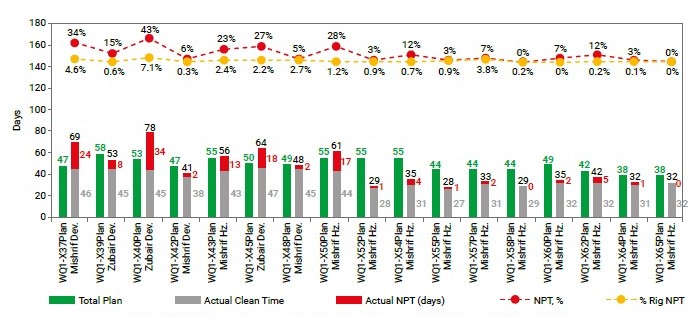
Fig. 17. Wells performance in the West Qurna-1 Field from 2017 to 2018
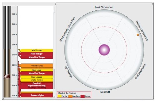
Fig. 18. Drilling optimization through real-time monitoring of drilling problems from the Mishrif to Mauddud Formations
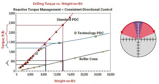
Fig. 19. Reactive torque management with weight on bit
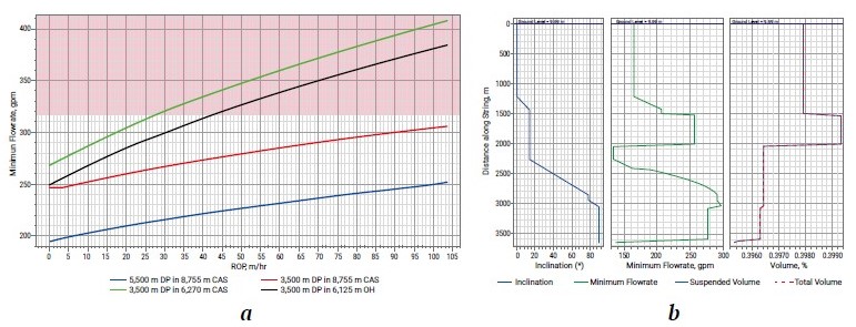
Fig. 20. Hole cleaning performance: Minimum flow rate vs ROP – a, and Inclination, flow rate, and volume % for the Mauddud Formation in the West Qurna Field – b
Conclusion(s)
- The use of the 16” SFD75D bit in directional wells proved to be the preferred bit for this section. Toward improving performance, the 16” MMD65R, EQH16R, and SF74R bits can also be successfully useable. It is recommended to use the MME65R PDC bit as a primary or backup in upcoming Mishrif horizontal wells in southern Iraq. The MSi616L bit type is a well-proven design for drilling 12¼” section applications in southern Iraq, while the EQH12DR bit type was used in recent drilling operations to complete the remaining parts of the 8.5" section and came out in excellent condition. For horizontal sections, the MMD54 bit (5 blades, 13 mm cutter size) showed excellent performance and accumulated intervals, achieving the highest ROP (26.9 m /hr).
- Changes in the drilling program include running a 12¼” rotary slick BHA with large nozzles and pumping a balanced cement plug through the bit to drill up to 2000 m. In the case of Dammam Formation losses, LCM will be pumped, and a cement plug will be pumped if needed. Then POOH and run an open-ended drill pipe to set the cement plug. Finally, POOH and directional BHA were run to drill to TD. ECD must be controlled, and MW must be optimized before penetrating the Hartha Formation. To minimize losses, high overbalance must be avoided while drilling Hartha, and losses with LCM can be cured.
- Several successful FlexPlug applications have been completed in southern Iraq fields, providing valuable experience in treating serious lost circulation situations.
- Only 10m is required to drill below the top of the Sadi Formation, after which losses must be checked before continuing drilling. PP/FG data must be optimized and updated from the top section as a guide and trend for the bottom interval. The hole must be cleaned, and flow and POOH must be checked.The 12 1/4'' section in the Hartha Formation must be drilled with directional BHA in rotary mode with controlled parameters.
- Sudden losses in the Tanuma Formation must be managed, and the hole must keep full at all times to prevent the collapse of weak zones. Shale inhibition must be added to the bridging material to control effective shale formations.
- In the Mauddud Formation, good hole cleaning can be achieved with 250–317 gpm in the horizontal section at a rotary speed of 40 RPM, a settling velocity at 10.2 ft/min, and a Yield point of 3.933 lft/100ft2.
- The suggested parameters before starting to drill the Nahr Umr Formation are a flow rate of 2500–3500 l/min, WOB of 12–15 tons, RPM of 100–160, and MW of 1.25 sg to avoid potential sticking of the pipes and hole sloughing.
- The mud loss problem will be noticeable in the north of the West Qurna-1 and south of the West Qurna-2 Field, while it will be partial toward the south due to the mud loss in the Shuaiba Formation.
- The 7” production liner must be run and seated with proper isolation across the Mishrif and Zubair Formations. The liner must be overlapped to prevent potential communication between the lower water‐bearing zones and shallow loss zones during well production.
- The drilling fluid density is 1.28 sg from the top to the bottom of the Zubair and Mishrif Formations, with full holes at all times. Tripping in/out must be done at controlled speeds to prevent surging/swabbing the well. Frequent flow checks must be performed during drilling breaks, and gas from connections, background, and trips must be monitored. Potassium chloride must be added and maintained at 3 - 5% as per the program while drilling all sections of the Zubair Formation.
- For the Yamama Formation, the PDC bit (MMD65R) performed the best. Mud properties should have an MW of 1.60 - 1. 65 sg, GEM™ GP shale stabilizer/ KCl Polymer (5% KCL) must be added, with a flow rate of 1800-2300 LPM, and RPM as per DD's recommendations. An H2S Scavenger is recommended.
- The injector(s) should remain shut in until the Mishrif, Mauddud, Zubair, and Yamama Formations are cased off to prevent potential flow.
- The Dammam Formation faced the most drilling problems, while no significant problems occurred in the Dibdibba, Khasib, Rumaila, Ahmedi, and Mauddud Formations.
References
1. Aldamzharov N. Prevention of accidents and complications during drilling of branched horizontal boreholes. News of Science of Kazakhstan. 2017;(3):78–90. (In Russ.) URL: https://vestnik.nauka.kz/storage/docs/2017/2017_NNK_%E2%84%963_End.pdf
2. Nazari T., Hareland G., Azar J. Review of cuttings transport in directional well drilling: systematic approach. In: SPE Western Regional Meeting. May 27–29, 2010, Anaheim, California, USA. https://doi.org/10.2118/132372-MS
3. Hashim J., Abdulkadir U., Alkali M., Kumar A. Basic drilling problems and optimization by general intensive knowledge. International Journal for Advance Research and Development. 2017;2(5):90–101. URL: https://www.ijarnd.com/manuscripts/v2i5/V2I5-1173.pdf
4. Salih A, Hussein H. Artificial intelligent models for detection and prediction of lost circulation events: a review. Iraqi Journal of Chemical and Petroleum Engineering. 2022;23(4):81–90. https://doi.org/10.31699/IJCPE.2022.4.10
5. Miranda C., Oliveira J., Cavalcante G. et al. Materials for controlling severe lost circulation-laboratory evaluation. In: SPE Latin America and Caribbean Petroleum Engineering Conference. May 17–19, 2017, Buenos Aires, Argentina. https://doi.org/10.2118/185582-MS
6. Caughron D., Renfrow D., Bruton J. et al. Unique crosslinking pill in tandem with fracture prediction model cures circulation losses in deepwater Gulf of Mexico. In: IADC/SPE Drilling Conference. February 26–28, 2002, Dallas, Texas. https://doi.org/10.2118/74518-MS
7. Toreifi H., Rostami H., Manshad A. New method for prediction and solving the problem of drilling fluid loss using modular neural network and particle swarm optimization algorithm. Journal of Petroleum Exploration and Production Technology. 2014;4:371–379. https://doi.org/10.1007/s13202-014-0102-5
8. Bloys B., Davis N., Smolen B. et al. Designing and managing drilling fluid. Oilfield Review. 1994;6(2):33–43.
9. Yarim G., Uchytil R., May R. et al. Stuck pipe prevention – a proactive solution to an old problem. In: SPE Annual Technical Conference and Exhibition. November 11–14, 2007, Anaheim, California, USA. https://doi.org/10.2118/109914-MS
10. Muqeem M., Weekse A., Al-Hajji A. Stuck pipe best practices – a challenging approach to reducing stuck pipe costs. In: SPE Saudi Arabia Section Technical Symposium and Exhibition. April 8–11, 2012, Al-Khobar, Saudi Arabia. https://doi.org/10.2118/160845-MS
11. Salminen K., Cheatham C., Smith M., Valiullin K. Stuck-pipe prediction by use of automated real-time modeling and data analysis. SPE Drilling & Completion. 2017;32(03):184–193. https://doi.org/10.2118/178888-PA
12. Saleh I., Khalaf A., Al-Jawad M. Southern Iraqi Oil fields drilling problems identification, analysis, and treatment. In: Offshore Technology Conference Asia. March 20–23, 2018, Kuala Lumpur, Malaysia. https://doi.org/10.4043/28597-MS
13. Al-Dujaili A. N., Sundos H. A Statistical survey for drilling problems at North Rumaila field, Southern Iraq. A review enhanced with well logs analyses. Jordan Journal of Earth and Environmental Sciences. 2023. (In press.)
14. Sissakian V. Geological evolution of the Iraqi Mesopotamia Foredeep, inner platform and near surroundings of the Arabian Plate. Journal of Asian Earth Sciences. 2013;72:152–163. https://doi.org/10.1016/j.jseaes.2012.09.032
15. Fouad S., Wafa'a A. Tectonic and structural evolution of Al-Jazira Area. Iraqi Bulletin of Geology and Mining. 2009;(3):33–48.
16. Fouad S. Tectonic and structural evolution of the Mesopotamia Foredeep, Iraq. Iraqi Bulletin of Geology and Mining. 2010;6(2):41–53.
17. Handhal A.., Jawad S, Al-Abadi A. GIS-based machine learning models for mapping tar mat zones in upper part (DJ unit) of Zubair Formation in North Rumaila supergiant oil field, Southern Iraq. Journal of Petroleum Science and Engineering. 2019;178:559–574. https://doi.org/10.1016/j.petrol.2019.03.071
18. Al-Khafaji A., Yonis S., Ibrahim R. et al. Geochemical characterization and origin of the Cretaceous Sa’di, Khasib, Mishrif, and Nahr Umr Crude Oils in Halfaya Oilfield, Southern Mesopotamian Basin, Iraq. Petroleum Science and Technology. 2021;39(21–22):993–1007. https://doi.org/10.1080/10916466.2021.1980587
19. Abeed Q., Leythaeuser D., Littke R. Geochemistry, origin and correlation of crude oils in Lower Cretaceous sedimentary sequences of the southern Mesopotamian Basin, southern Iraq. Organic Geochemistry. 2012;46:113–126. https://doi.org/10.1016/j.orggeochem.2012.02.007
20. Mehenni M., Guit F. Majnoon Field, SE Iraq: A giant unique among other giants? In: First EAGE Workshop on Iraq-Hydrocarbon Exploration and Field Development. 2012. https://doi.org/10.3997/2214-4609.20143558
21. Abbas M., Watheq J. Lithofacies classification of carbonate reservoirs using advanced machine learning: a case study from a Southern Iraqi oil field. In: Offshore Technology Conference. August 16–19, 2021, Virtual and Houston, Texas 2021. https://doi.org/10.4043/31114-MS
22. Al-Ameri T., Jafar M., Janet P. Hydrocarbon generation modeling of the Basrah oil fields, Southern Iraq. AAPG Annual Convention and Exhibition. April 10-13, 2011, Houston, Texas. 2011;20116.
23. Salih T., Sahi S., AL-Dujaili A. Using different surfactants to increase oil recovery of Rumaila field (experimental work). Iraqi Journal of Chemical and Petroleum Engineering. 2016;17(3):11–31. https://doi.org/10.31699/IJCPE.2016.3.2
24. Al-Ansari R. The petroleum geology of the upper sandstone member of the Zubair Formation in the Rumaila South. Geological Study, Ministry of Oil, Baghdad, Iraq. 1993.
25. Jassim S., Goff J. Geology of Iraq. Geological Society of London; 2006. 341 p.
26. Al-Ameri T., Jafar M., Pitman J. Hydrocarbon generation modeling of the Basrah oil fields, Southern Iraq. In: AAPG Annual Convention and Exhibition. March, 2012, Houston, Texas. 2012;20116:2011. https://doi.org/10.3997/2214-4609-pdb.287.1176781
27. Al-Dujaili A., Shabani M., Al-Jawad M. Characterization of flow units, rock and pore types for Mishrif Reservoir in West Qurna oilfield, Southern Iraq by using lithofacies data. Journal of Petroleum Exploration and Production Technology. 2021; 11, 4005–4018. https://doi.org/10.1007/s13202-021-01298-9
28. Al-Dujaili A., Shabani M., Al-Jawad M. Lithofacies and electrofacies models for Mishrif Formation in West Qurna Oilfield, Southern Iraq by deterministic and stochastic methods (comparison and analyzing). Petroleum Science and Technology. 2024;42(13):1656–1684. https://doi.org/10.1080/10916466.2023.2168282
29. Al-Dujaili A., Shabani M., Al-Jawad M. Lithofacies, deposition, and clinoforms characterization using detailed core data, nuclear magnetic resonance logs, and modular formation dynamics tests for Mishrif formation intervals in West Qurna/1 Oil Field, Iraq. SPE Reservoir Evaluation & Engineering. 2023;1–13. https://doi.org/10.2118/214689-PA
30. Al-Dujaili A., Shabani M., AL-Jawad M. Effect of heterogeneity on capillary pressure and relative permeability curves in carbonate reservoirs. a case study for Mishrif Formation in West Qurna/1 Oilfield, Iraq. Iraqi Journal of Chemical and Petroleum Engineering. 2023;24(1):13–26. https://doi.org/10.31699/IJCPE.2023.1.3
31. Lazim A., Maki M., Tariq S. Detect faults of Zubair and Mishrif Formations–Zubair Oilfield by Integrate Structural Geology and Pressure Transient Analyses (PTA) to Selected Wells. IOSR Journal of Applied Geology and Geophysics. 2020;8(5):67–72. https://doi.org/10.9790/0990-0805016772
32. Al-Jaberi M., A-Jafar M. Elements distribution for the upper sandstone member of the Zubair Formation in Zubair oil field, southern Iraq. Iraqi Geological Journal. 2020;53(1E):55–74. https://doi.org/10.46717/igj.53.1E.5Ry-2020-07-05
33. Hussein M., Eren T., Rahman A. et al. Case Study for Curing Circulation Losses during Primary Cementing Operations Using Fiber Cement in Zubair Field/Iraq. In: SPE/IADC Middle East Drilling Technology Conference and Exhibition. 29–31 January 2018, Abu Dhabi, UAE. 2018. https://doi.org/10.2118/189339-MS
34. Zainab M., Almallah I., Al-Najm F. Petrophysical properties evaluation using well logging of the upper sand member of Zubair Formation in Zubair oil Field, Southern Iraq. Basrah Journal of Science. 2019;37(3):456–480. Retrieved from https://www.basjsci.net/index.php/bsj/article/view/108
35. Al-Dujaili A., Shabani M., AL-Jawad M. Identification of the best correlations of permeability anisotropy for Mishrif reservoir in West Qurna/1 oil Field, Southern Iraq. Egyptian Journal of Petroleum. 2021;30(3):27–33. https://doi.org/10.1016/j.ejpe.2021.06.001
36. Sadooni F., Alsharhan A. Stratigraphy, microfacies, and petroleum potential of the Mauddud Formation (Albian–Cenomanian) in the Arabian Gulf basin. AAPG bulletin. 2003;87(10):1653–1680. https://doi.org/10.1306/04220301111
37. Cross N., Goodall I., Hollis C. et al. Reservoir description of a mid-Cretaceous siliciclastic-carbonate ramp reservoir: Mauddud Formation in the Raudhatain and Sabiriyah fields, North Kuwait. GeoArabia. 2010;15(2):17–50. https://doi.org/10.2113/geoarabia150217
38. Beydoun Z. Productive Middle East clastic oil and gas reservoirs: their depositional settings and origins of their hydrocarbons. In: Sedimentary Facies Analysis: a Tribute to the Research and Teaching of Harold G. Reading. Wiley; 1995. Pp. 329–354. https://doi.org/10.1002/9781444304091.ch14
39. Ibrahim M. W. Lithostratigraphy and subsurface geology of the Albian rocks of south Iraq. Journal of petroleum geology. 1981;4(2):147–162. https://doi.org/10.1111/j.1747-5457.1981.tb00530.x
40. Al-Zaidy A., Al-Mafraji T. Geohistory analysis and basin development of the Late Berriasian-Aptian Succession, Southern Iraq. Iraqi Geological Journal. 2019;52(2):36–52. https://doi.org/10.46717/igj.52.2.3Ms-2019-12-26
41. Idan R., Faisal R., Nasser M. et al. Hydrocarbon potential of Zubair Formation in the south of Iraq. Arabian Journal of Geosciences. 2015;8:4805–4817. https://doi.org/10.1007/s12517-014-1569-6
42. Al-Ghuribawi M., Rasha F. An Integrated Microfacies and Well Logs-Based Reservoir Characterization of Yamama Formation, Southern Iraq. Iraqi Journal of Science. 2021;62(10):3570–3586. https://doi.org/10.24996/ijs.2021.62.10.16
43. Chafeet H. Yamama reservoir characterization in the West Qurna oil field, Southern Iraq. Iraqi Journal of Science. 2016;57(2A):938-947.
44. Aqrawi A., Mahdi T., Sherwani G., Horbury A. Characterization of the Mid-Cretaceous Mishrif Reservoir of the southern Mesopotamian Basin, Iraq. In: American Association of Petroleum Geologists Conference and Exhibition. 7–10 March 2010; Manama, Bahrain. Pp. 7–10. https://doi.org/10.3997/2214-4609-pdb.248.104
45. Al-Iessa I., Zhang W. Facies evaluation and sedimentary environments of the Yamama Formation in the Ratawi oil field, South Iraq. Scientific Reports. 2023;13(1):5305. https://doi.org/10.1038/s41598-023-32342-9
46. Al-Dujaili A. N., Shabani M., Al-Jawad M. S. The efficient and economical application of a cement slurry programme for sandstone and carbonate reservoirs. A case study of the Zubair, Mauddud, and Mishrif formations in a supergiant oilfield, in southern Iraq. Bulletin of Geophysics & Oceanography. 2024;65(3):439–460. https://doi.org/10.4430/bgo00450
About the Author
A. N. Al-DujailiIraq
Ahmed N. Al-Dujaili – PhD, Doctor, Petroleum Engineering Department
Najaf, Iraq
Scopus ID 57224971849
Review
For citations:
Al-Dujaili A.N. New advances in drilling operations in sandstone, shale, and carbonate formations: a case study of five giant fields in the Mesopotamia Basin, Iraq. Mining Science and Technology (Russia). 2024;9(4):308-327. https://doi.org/10.17073/2500-0632-2023-08-146


