Scroll to:
Mechatronic system for running-in and testing of mechanical transmissions in mining shovels
https://doi.org/10.17073/2500-0632-2024-05-262
Abstract
The mechanical transmissions of the hoist and drag winches, as well as the crowd mechanisms of mining shovels, operate under highly variable and shock cyclic loads. These severe operating conditions impose stringent quality requirements on both the manufacturing and assembly of such transmissions. The lifecycle management process for these gearboxes includes running-in and acceptance testing at the manufacturing plant, followed by diagnostics and condition monitoring during field operation. Test benches designed for these purposes must closely replicate the operating conditions experienced by the transmission in actual service. The developed test bench is designed to perform running-in (initial wear-in of mating surfaces) and quality control testing of hoist and crowd winch gearboxes installed in electric mining shovels of the following models: EKG-8US, EKG-10, EKG-12K, EKG-15M, EKG-18, EKG-20KM, and EKG-32R. These operations are carried out as part of the standard acceptance testing procedure. The test bench is equipped with DC excavator motors rated at 350 kW (drive motors) and 560 kW (loading motor). The hoist winch gearbox from the EKG-15M shovel serves as the torque multiplier. Two intermediate shafts are connected via an intermediate coupling, with the loading motor driving one of these shafts. Motor control is implemented using standard DC transistor converters with PWM control, identical to those used in mining shovels equipped with DC main drives. The running-in and testing processes are carried out using the mutual loading method, which enhances energy efficiency by allowing regenerative energy to be reused within the system. The test bench software is based on the Pulsar-7 information and diagnostics system, which supports the following operational modes: 1. Interactive manual control, enabling the operator to verify the functionality and calibration of test bench components. 2. Automatic control of the running-in and testing processes, where pre-programmed sequences from a built-in library generate the required control commands for each specific test type. Available test modes include: unloaded running-in, running-in under constant load, running-in under variable load and rotational speed, excavation cycle simulation. 3. Automated test report generation, including the ability to view and print previously generated reports. 4. Software configuration and auxiliary functions, including an embedded help system. A mathematical model of the mechatronic system was developed and used to simulate the running-in process of the EKG-15M crowd gearbox in Simulink. The developed test bench system has been successfully implemented at Joint Power Co., Ltd. (Moscow) and IZ-KARTEX named after P.G. Korobkov.
Keywords
For citations:
Malafeev S.I., Malafeeva A.A., Konyashin V.I., Novgorodov A.A. Mechatronic system for running-in and testing of mechanical transmissions in mining shovels. Mining Science and Technology (Russia). 2025;10(1):75-83. https://doi.org/10.17073/2500-0632-2024-05-262
Mechatronic system for running-in and testing of mechanical transmissions in mining shovels
Introduction
The mechanical transmissions of mining shovels and other mining machinery are critical components that significantly affect the reliability and operational efficiency of these machines [1, 2]. The hoist and drag winch gearboxes, as well as the crowd mechanisms, are subjected to highly variable cyclic shock loads during operation. These loads accelerate wear and reduce the service life of gearboxes. Consequently, stringent manufacturing quality requirements are applied to their transmission components [3]. The lifecycle management of such gearboxes includes running-in and acceptance testing at the manufacturer’s site, followed by diagnostics and condition monitoring during field operation [4, 5]. The integration of digital twin technology offers promising prospects, enabling the creation of digital gearbox models and their verification during running-in and acceptance testing [6].
The running-in process serves several purposes, including initial wear-in of mating surfaces, detection of assembly defects, and adjustment of components and assemblies, all of which contribute to extending the service life of the gearboxes [7, 8]. Running-in plays a key role in ensuring stable performance of mechanical systems, acting as a transitional process that involves complex interactions between friction, lubrication, surface roughness, plastic deformation, and wear [9, 10]. During this process, key tribological parameters (such as surface roughness, surface texture, friction coefficient, and wear rate) evolve until they stabilize under steady-state conditions [11, 12]. The final tribological state achieved during running-in largely determines the long-term performance characteristics of the gearbox [13]. The running-in process is developed individually for each gearbox type, involving a stepwise sequence of modes, from no-load operation to operation under nominal load, covering various speeds and rotational directions [14, 15]. The duration of running-in and testing depends on the specific design and operating conditions of the gearbox.
Test benches designed for running-in and testing must be capable of simulating all required test modes, automating test execution and data processing, and minimizing energy consumption [14, 15]. Test benches must closely replicate the actual operating conditions of the mechanical transmission during testing. Currently, the mutual loading method using electric machines is the most widely used approach for gearbox testing, where the shafts are connected via a gearbox and a torque multiplier[1]. This method uses identical drive motors and mechanical transmissions (gearbox and multiplier). For manufacturers producing a variety of gearbox designs, the ability to test units with different gear ratios is particularly important [16].
This paper examines the design and implementation of an automated system for the running-in and testing of hoist and crowd winch gearboxes for mining shovels, developed by Joint Power Co., Ltd. (Moscow).
[1] Malafeev S. I. Russian Patent No. 2779712. IPC G01R31/34. Test Bench for DC Electric Machines and Mechanical Transmissions. Published on September 12, 2022. Bulletin No. 26.
Objective and tasks
The objective of this study is to analyze, design, and model test bench equipment for the running-in and testing of mechanical transmissions used in the main drives of electric mining shovels.
Key tasks:
- to develop of functional diagrams for test benches for the running-in of hoist and crowd winch gearboxes in mining shovels, ensuring that the benches are effective for testing mechanical transmissions of different excavator models with various gear ratios;
- to develop and analyze the mathematical models describing the mechatronic systems of test benches for the running-in of gearboxes in both single-motor and dual-motor drives, using the mutual loading method;
- to study the mechatronic system models of the test benches using MATLAB-Simulink;
- to implement the mechatronic system for the test bench at IZ-KARTEX named after P.G. Korobkov.
1. Functional diagram of the system
The functional diagram of the mechatronic system for the running-in of dual-motor hoist drive gearboxes is shown in Fig. 1. The mechatronic system is powered by the 0.4 kV plant power supply network through the circuit breaker QF, power transformer T, and diode rectifier R. A capacitor C is installed in the DC link. The tested gearbox is driven by two DC motors — M1 and M2. The low-speed shaft of the gearbox G is connected to the shaft of the loading motor M3 via a torque multiplier MP. The motors M1, M2, and M3 are controlled by regulating the voltage applied to their armature windings using transistor bridge converters – TC1, TC2, and TC3, respectively. The field windings of the motors are connected in series and powered by the output of the transistor converter TCO. A transistor switch TS and ballast resistor R are used to dissipate excess energy in the DC link in case of emergency. The torque on the motor shafts is measured using torque couplings MM1 and MM2. The testing process is controlled by a dedicated operator PC, with all test programs and results stored on a server.
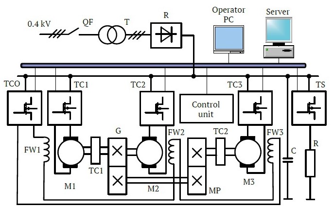
Fig. 1. Functional diagram of the mechatronic system for running-in hoist gearboxes: QF – circuit breaker; T1 – power transformer; R – rectifier; TCO, TC1, …, TC3 – transistor bridge converters; TS – transistor switch; С – DC link capacitor; BR – ballast resistor; M1 – loading DC motor; М2, М3 – drive DC motors; FW1, …, FW3 – field windings of motors M1, M2, M3, respectively; MP – torque multiplier; G – tested gearbox; TC1, TC2 – torque measuring couplings
The test bench uses power equipment and an information and control system originally developed for mining shovels equipped with DC main drives and transistor power converters [17].
The running-in and testing of the gearboxes is carried out using the mutual loading method. The power inputs of the transistor converters TC1, TC2, and TC3 are connected in parallel to the DC link. The field windings of the electric machines are supplied by the output of TCO, which operates in current stabilization mode. Motors M1 and M2 operate in motor mode, controlled by a dual-loop control system, consisting of an inner current loop and an outer voltage loop [17, 18]. To stabilize the angular speed, positive feedback from the armature current is used. In this configuration, one motor acts as the master, while the other follows as the slave. Motor M3 operates in generator mode, maintaining constant armature current. The power take-off points from the DC link for all drives are unified, meaning that the power drawn from the network equals the losses in the electric machines and the transistor converters. For the running-in and testing of crowd winch gearboxes, only a single drive motor is used – for example, M1.
The test bench configuration shown in Fig. 1 allows for the running-in and testing of gearboxes with different gear ratios using a single stationary torque multiplier.
2. Analysis of the test bench mechatronic system
The structural diagram of the mechatronic system for the test bench is shown in Fig. 2. The designations used in the diagram are as follows: TC1, TC2, TC3 – transistor converters for motor control; ACS1, ACS2, ACS3 – armature current sensors of the DC motors; CR1, CR2, CR3 – current regulators; VR – voltage regulator; CL – current limiter unit; IS1, IS2 – intensity setpoints; Hс1(s), Hс2(s), Hс3(s) – transfer functions of the transistor converters controlling DC motors M1, M2, M3, respectively; Hcur1(s), Hcur2(s), Hcur3(s) – transfer functions of the current regulators; Hv(s) – transfer function of the voltage regulator in the speed control system; kcur – gain of the corrective positive current feedback; Hf(s) – transfer function of the filter in the voltage control loop; r1, r2, r3 – armature winding resistances of the DC motors; L1, L2, L3 – armature winding inductances of the DC motors; c1, c2, c3 – motor constants of the DC motors; ki1, ki2, ki3 – gains of the current sensors DT1, DT2, DT3, respectively; ku – gain of the voltage sensor; J1 – equivalent moment of inertia of the rotating masses referred to the drive motor shaft; J2 – equivalent moment of inertia referred to the loading motor shaft; km1 and km2 – transmission ratios of the gearbox and the torque multiplier, respectively; c12 – stiffness of the mechanical connection; kv1, kv2 – viscous friction coefficients simulating losses in the mechanical transmissions; U1, U2, U3 – armature voltages of the electric machines; i1, i2, i3 – armature currents of the electric machines; Ω1 and Ω2 – angular speeds of the drive motors and the loading machine, respectively; φ1 and φ2 – rotation angles of the gearbox output shaft and the torque multiplier input shaft; T1 and T2 – electromagnetic torques of the first and second drive motors; T – torque at the gearbox output shaft; uss – speed setpoint voltage for the drive motors; ucs – load torque setpoint voltage (armature current setpoint for the loading motor). For the transistor converters, the following applies: Hc1(s) = kc1, Hc2(s) = kc2, Hc3(s) = kc3, where kc1, kc2, kc3 are the gains of the corresponding converters. The control system uses a proportional voltage regulator with a gain of kv, i.e., Hv(s) = kv, and a first-order low-pass filter
![]()
where kf and Tf are the filter gain and time constant, respectively. Proportional-integral controllers are used as current regulators.
In the dual-motor drive, identical electric machines are used, so Hp1(s) ≈ Hp2(s); Ht1(s) ≈ Hт2(s); r1 ≈ r2; L1 ≈ L2; c1 ≈ c2; kt1 ≈ kt2. For crowd gearbox testing, only one drive motor is used (Fig. 3).
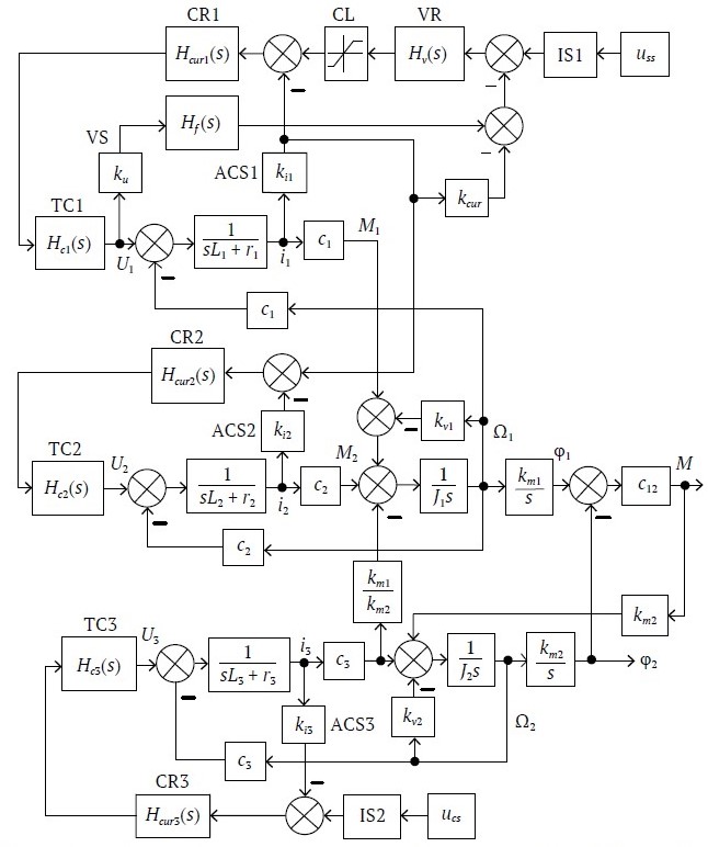
Fig. 2. Structural diagram of the mechatronic system for running-in the hoist winch gearbox
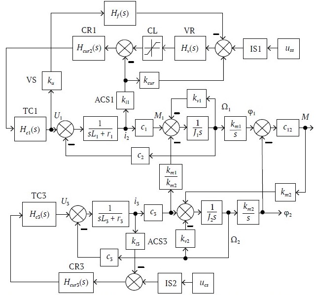
Fig. 3. Structural diagram of the mechatronic system for running-in the crowd winch gearbox
The power drawn from the supply network under steady-state running-in conditions equals the total power losses in the powertrain components. For the system shown in Fig. 2, the total power drawn from the supply can be expressed as:
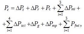
where ∆Pt – transformer losses; ∆Pr – rectifier losses; Pc – losses in the DC link capacitor;

total losses in the electric machines;

total losses in the transistor converters; ∆Pg – gearbox losses; ∆Pmp – torque multiplier losses; –

active power consumed by the field windings of the electric machines.
The losses in each component can be approximately determined using their efficiency values under the corresponding operating modes.
3. Mechatronic system modeling
The system model was studied using Simulink during the running-in process of the EKG-15M crowd winch gearbox. The simulation was performed for a system equipped with DC motors M1 (DPE350D-2) and M3 (DPE560D-2). The gear ratio of the crowd gearbox is 92.59, and the transmission ratio of the torque multiplier is 31.359.
Figs. 4 and 5 show the results of the simulation for the running-in process of the EKG-15M crowd gearbox (with a gear ratio of 92.59). Fig. 4 presents oscillograms of system processes at different angular speeds and load torques. During the time interval from 0 to 40 seconds, the drive accelerates to an angular speed of 20 rad/s, with a load torque of 1.6 kN·m applied to the low-speed shaft. At 40 seconds, the angular speed increases to 30 rad/s, while the load torque at the output shaft remains 1.6 kN·m. At 80 seconds, the angular speed of the drive motor increases to 50 rad/s. At 120 seconds, the load torque increases to 9 kN·m, and at 160 seconds, the load torque further rises to 16.5 kN·m.
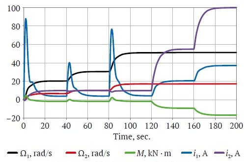
Fig 4. Oscillograms recorded during the running-in of the crowd winch gearbox at different angular speeds and load torques
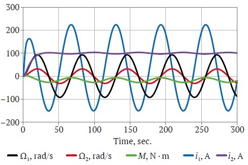
Fig. 5. Oscillograms recorded during the running-in of the crowd winch gearbox under harmonic variation of the drive motor’s angular speed and constant load torque
Fig. 5 shows oscillograms of the mechatronic system’s processes during harmonic variation of the drive motor’s angular speed, with a period of 62.8 seconds. Throughout the process, the loading machine maintains a constant torque, with its armature current set at 100 A. During the first half of the cycle, the load torque acts as a braking force. In the second half, it aligns with the torque produced by the drive motor.
4. Practical implementation of the test bench
The developed test bench is designed for the running-in process (initial wear-in of mating surfaces) and quality control testing of hoist and crowd winch gearboxes used in electric mining shovels of the following models: EKG-8US, EKG-10, EKG-12K, EKG-15M, EKG-18, EKG-20KM, and EKG-32R. These operations are performed as part of the acceptance testing procedure. An external view of the test bench is shown in Fig. 6.
The test bench is equipped with DC excavator motors, including two 350 kW drive motors and one 560 kW loading motor. The hoist winch gearbox from the EKG-15M excavator serves as the torque multiplier, with a gear ratio of 31.359. The system includes two intermediate shafts, which are linked by an intermediate coupling, and the loading motor is connected to one of these shafts. Motor control is handled by standard DC transistor converters with pulse-width modulation (PWM) — the same type of converters used in mining shovels with DC main drives [17]. Drive motor speed range: 0 to 1000 rpm. Load torque range at the loading motor output shaft: 0 to 7.5 kN·m.
The test bench software is based on the Pulsar-7 information and diagnostics system [17], supporting the following operating modes:
Interactive manual control of test bench components. In manual mode, the operator can check the functionality of the bench components and perform calibration. The software automatically detects the status of the circuit breakers (indicating whether they have tripped) and verifies the readiness of the power converters and monitoring instruments.
Automatic control of the running-in and testing process. Pre-programmed sequences from the built-in test library generate the required control commands for each specific test type. The software supports various modes, including no-load running-in, running-in under constant load, running-in with variable load and angular speed, and excavation cycle simulation [18]. The operator selects the desired mode via the computer interface. The current values of key monitored parameters — including the rotational speeds of the motors and gearbox shafts, torque, and motor currents — are displayed on the monitor in real time. During testing, the system automatically generates a test report for the tested unit, with data recorded to the hard disk in real time. The software also supports synchronized operation with external instruments used to monitor vibration levels, bearing temperatures, and kinematic deviations in gear meshing, among other parameters.
Test report generation. The operator can view and print any previously generated test reports. Each report includes: a text section listing the measurement results required by the test methodology for each specified mode; a graphical section, where the operator can select parameters to display their time-dependent trends recorded during the test.
Software configuration and auxiliary functions, including an integrated help system.
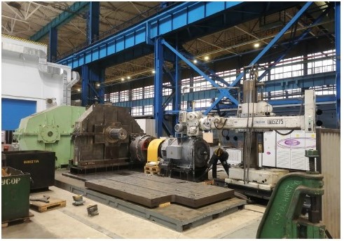
Fig. 6. Test bench installed in the workshop
Conclusions and recommendations
- The voltage stabilization algorithms under consideration rely on an analytical solution to the problem of power flow determination in the electrical system. Running-in and testing of mining shovel transmissions improve manufacturing quality and ensure that product characteristics meet the required specifications. Gearbox running-in enables the initial wear-in of mating surfaces, identifies assembly and installation defects, and allows for the adjustment of assembly units and components. The running-in mode is developed individually for each gearbox type. The process is carried out in several stages, ranging from no-load operation to operation under nominal load, at various speeds and directions of rotation.
- The developed equipment package ensures the implementation of all required test modes, automation of both testing processes and data processing, while also minimizing energy consumption. The test bench equipment allows for the running-in and testing of gearboxes with various gear ratios using a single setup: for hoist winch gearboxes, gear ratios range from 25.43 (EKG-10) to 82.56 (EKG-32); for crowd winch gearboxes, gear ratios range from 60 (EKG-10) to 90.6 (EKG-20K). Drive motor speed control range: 0 to 1000 rpm. Load torque control range at the output shaft of the loading motor: 0 to 7.5 kN·m. Test bench power supply voltage: 380 V; frequency: 50 Hz. Three-phase supply with grounded neutral. Power consumption: 400 kW.
- The mutual loading method used for the running-in and testing process ensures efficient use of electrical energy by utilizing regenerated energy.
- The test bench incorporates power equipment and the Pulsar-7 information and control system, both originally developed for mining shovels equipped with DC main drives and transistor power converters. The system supports both manual control of individual components and fully automated management of the running-in and testing processes.
- The successful deployment and operation of the test bench at IZ-KARTEX named after P.G. Korobkov confirms its high technical performance. The electrical equipment and software are recommended for use in organizing transmission testing for heavy mining machinery of various types.
References
1. Quan Z., Ge L., Wei Z., Li Y. W., Quan L. A survey of powertrain for energy-efficient heavy-duty machinery technologies. In: Proceedings of the IEEE. 2021;109(3):279–308. https://doi.org/10.1109/jproc.2021.3051555
2. Khoreshok A. A., Kudrevatykh A. V., Ashcheulov A. S. et al. Increasing life of pit dump truck motor-wheel gearboxes by introducing the monitoring of the actual technical condition. Mining Science and Technology (Russia). 2021;6(4):267–276. (In Russ.) https://doi.org/10.17073/2500-0632-2021-4-267-276
3. Drygin M. Yu., Kuryshkin N.P. Increasing the quality of excavators’ planetary reduction gearboxes on the basis of dimensional analysis and geometrical characteristics of tooth wheels. In: Journal of Physics: Conference Series, Volume 944, XI International scientific and technical conference "Applied Mechanics and Dynamics Systems". 14–16 November 2017, Omsk, Russian Federation. https://doi.org/10.1088/1742-6596/944/1/012030
4. Mao Y., Tong J., Chin Z. Y. et al. Transmission error and vibration-based condition monitoring of gear wear with contaminated lubricant.Wear. 2023;523:2047–2060. https://doi.org/10.1016/j.wear.2023.204760
5. Gericke B. L., Sushko A. E., Gericke P. B., Efremenkov A. B. Digital technologies used in technical diagnostics, assessment of technical condition, maintenance and repair of mining machines and equipment. In: Journal of Physics: Conference Series, Volume 2052, 3rd International Scientific and Practical Conference on Mathematical Modeling, Programming and Applied Mathematics (MMPAM 2021). 6–7 September 2021, Veliky Novgorod, Russia. https://doi.org/10.1088/1742-6596/2052/1/012016
6. Algin V. B., Ishin N. N. Reliability of technically complicated items in terms of "Industry 4.0". Topical Issues of Mechanical Engineering. 2017;(6):43–54. (In Russ.)
7. Blau P. J. On the nature of running-in. Tribology International. 2005;38(11–12):1007–1012. https://doi.org/10.1016/j.triboint.2005.07.020
8. Jamaria J., Ammarullaha M. I., Afifa I. Y. et al. Running-in Analysis of Transmission Gear. Tribologyin Industry. 2021;43(3):434–441. https://doi.org/10.24874/ti.1092.04.21.08
9. Voynov K. N. Generalizations in tribology. St. Petersburg: Publishing and Polygraphic Association of Higher Educational Institutions; 2024. 250 p. (In Russ.)
10. Kragelsky I. V., Kombalov V. S. Calculation of value of stable roughness after running-in (elastic contact). Wear. 1969;14(2):137–140.
11. Sjöberg S., Sosa M., Andersson M., Olofsson U. Analysis of efficiency of spur ground gears and the influence of running-in, Tribology International. 2016;93A:172–181. https://doi.org/10.1016/j.triboint.2015.08.045
12. Wang Q., Ma B., Liang Y. et al. Effects of operating conditions on the tribological behavior of a wet multi-disc clutch during the running-in process. Tribology International. 2023;179:108096. https://doi.org/10.1016/j.triboint.2022.108096
13. Khonsari M. M., Ghatrehsamani S.,Akbarzadeh S. On the running-in nature of metallic tribo-components: A review. Wear. 2021;474–475:203871. https://doi.org/10.1016/j.wear.2021.203871
14. Ivanov V. P. Running-in of gears of mining machines. Mining Mechanical Engineering and Machine-Building. 2016;(2):55–59.
15. Streltsov V. V., Popov V. N., Karpenkov V. F. Resource-saving accelerated running-in of repaired engines. Moscow: Kolos; 1995. 175 p. (In Russ.)
16. Gervais G. K. Industrial tests of electric machines. Leningrad: Energoatomizdat; 1984. 408 p.
17. Malafeev S. I., Serebrennikov N. A. Increasing energy efficiency of mining excavators through upgrade of electrical equipment and control systems. Ugol’. 2018;(10):30–34. (In Russ.) http://dx.doi.org/10.18796/0041-5790-2018-10-30-34
18. Malafeev S. I., Novgorodov A. A., Konyashin V. I. Bench tests of the quarry excavators main electric drives. In: XI International Conference on Electrical Power Drive Systems (ICEPDS). Saint-Petersburg, Russia, October 04–07, 2020. https://doi.org/10.1109/icepds47235.2020.9249257
About the Authors
S. I. MalafeevRussian Federation
Sergey I. Malafeev – Dr. Sci. (Eng.), Professor of the Department of Computer Engineering and Control Systems; Chief Scientific Officer
Vladimir; Moscow
A. A. Malafeeva
Russian Federation
Alevtina A. Malafeeva – Dr. Sci. (Eng.), Professor of the Department of Information Technology
Vladimir
Scopus ID 26422368500
V. I. Konyashin
Russian Federation
Vladimir I. Konyashin – Cand. Sci. (Eng.), Senior Researcher at the Innovation Department
Moscow
Scopus ID 56582464300
A. A. Novgorodov
Russian Federation
Andrey A. Novgorodov – Head of the Mechatronic Systems Design Department
Moscow
Scopus ID 57192383884
Supplementary files
Review
For citations:
Malafeev S.I., Malafeeva A.A., Konyashin V.I., Novgorodov A.A. Mechatronic system for running-in and testing of mechanical transmissions in mining shovels. Mining Science and Technology (Russia). 2025;10(1):75-83. https://doi.org/10.17073/2500-0632-2024-05-262
JATS XML


